

Summary
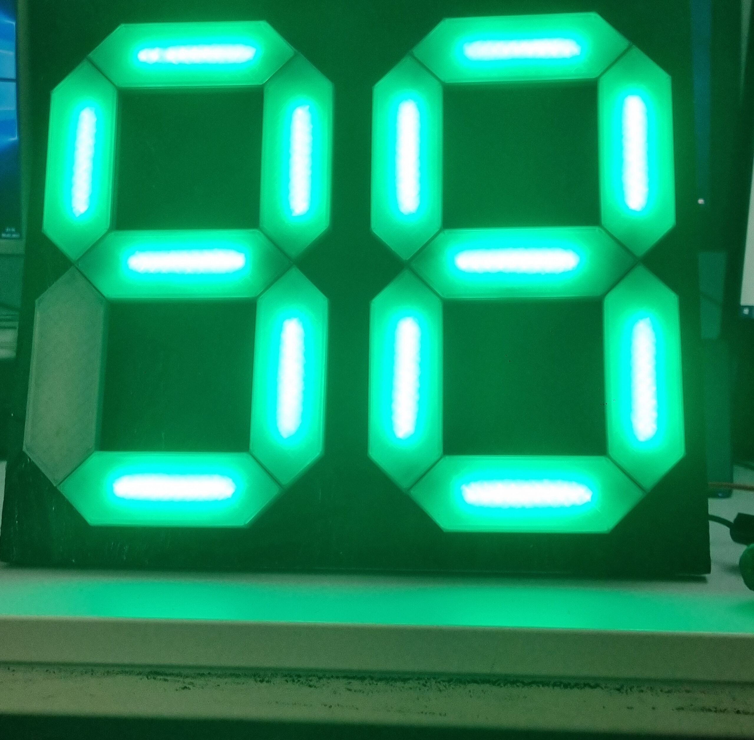
What workshop doesn’t have an air compressor? From impact wrenches and orbital sanders to pneumatic chisels, the potential energy of compressed air can be utilised in a variety of ways. Commercially available compressors usually work with a supply pressure of 8 to 12 bar. If too much air is released from the tank quickly, the supply pressure can even fall below 5 bar. But how can I find out the available pressure on the system? Small pressure gauges on the compressed air connections can provide information, but these are difficult to read from a few meters away. For this reason, we decided to build a large digital 2×7-segment display that shows the actual pressure. This display is clearly visible from any point in the workshop and, in addition to the numerical display, also shows the current pressure supply by means of an RGB colour change from red to green. It is controlled via an Arduino Nano with ATMega328 microcontroller. In addition to a 3D printer, transparent printing filament and a corresponding pressure sensor are required for construction. The material costs for this project amount to approx. 60 €.
Materials & Methods
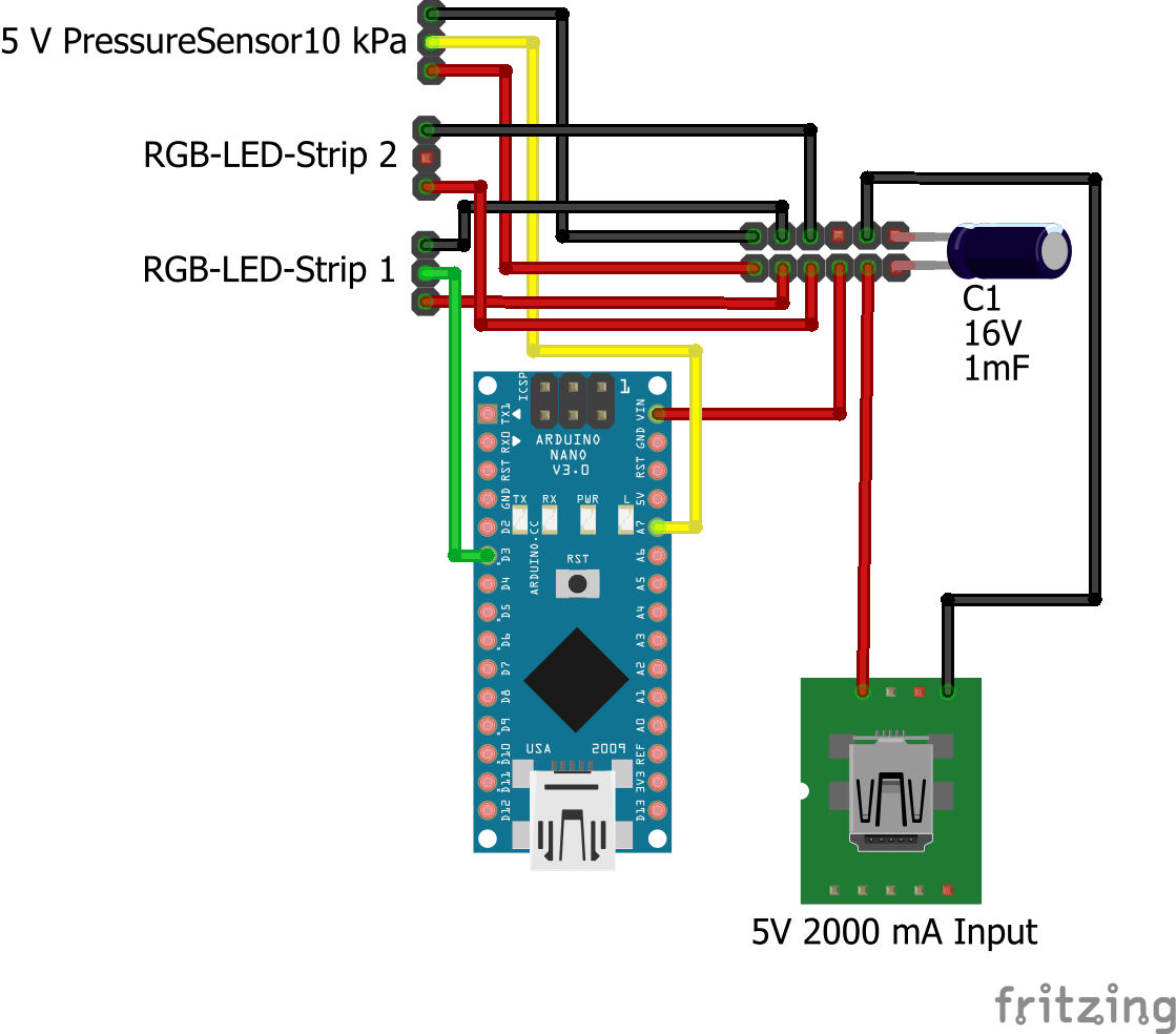
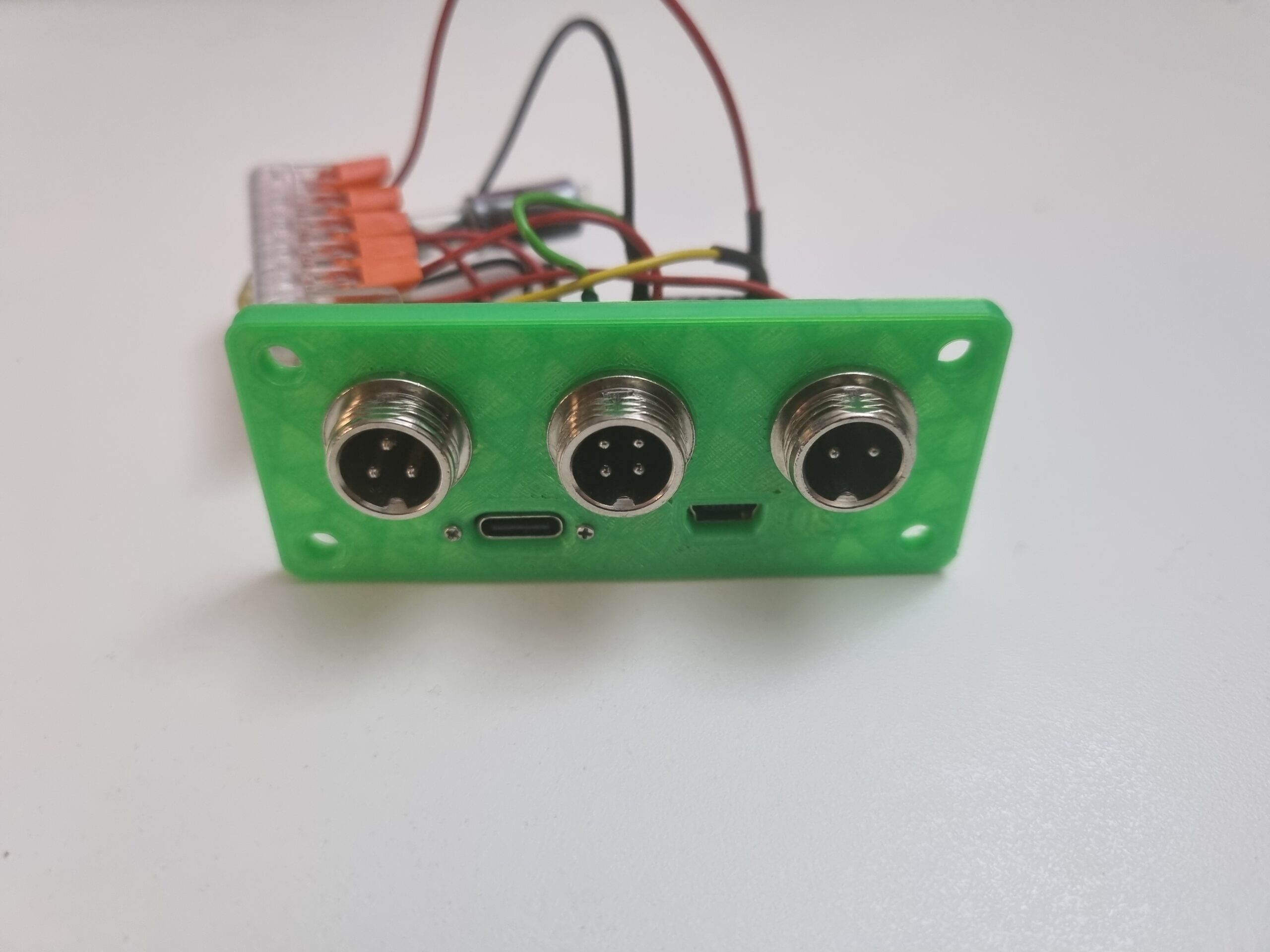
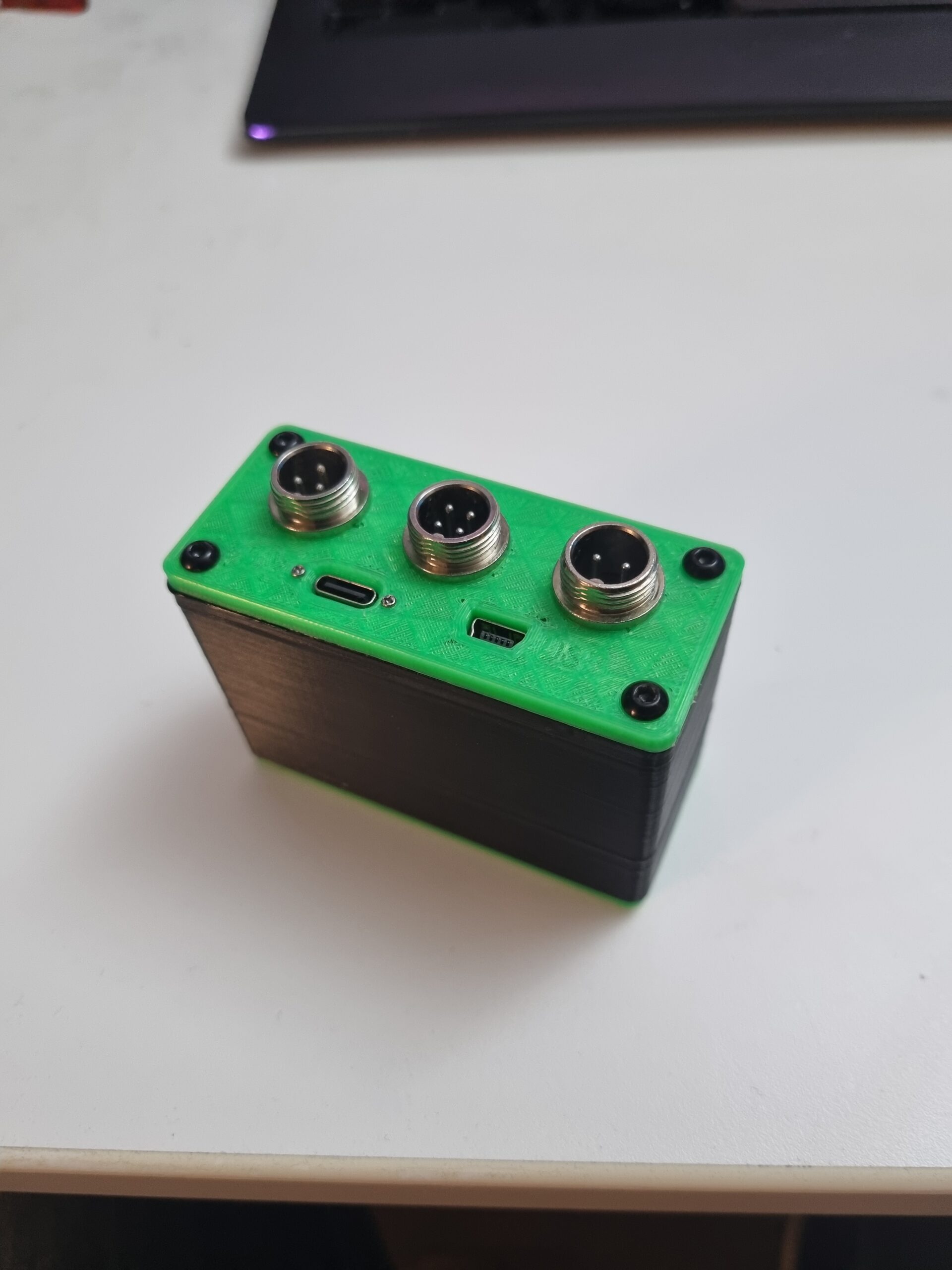
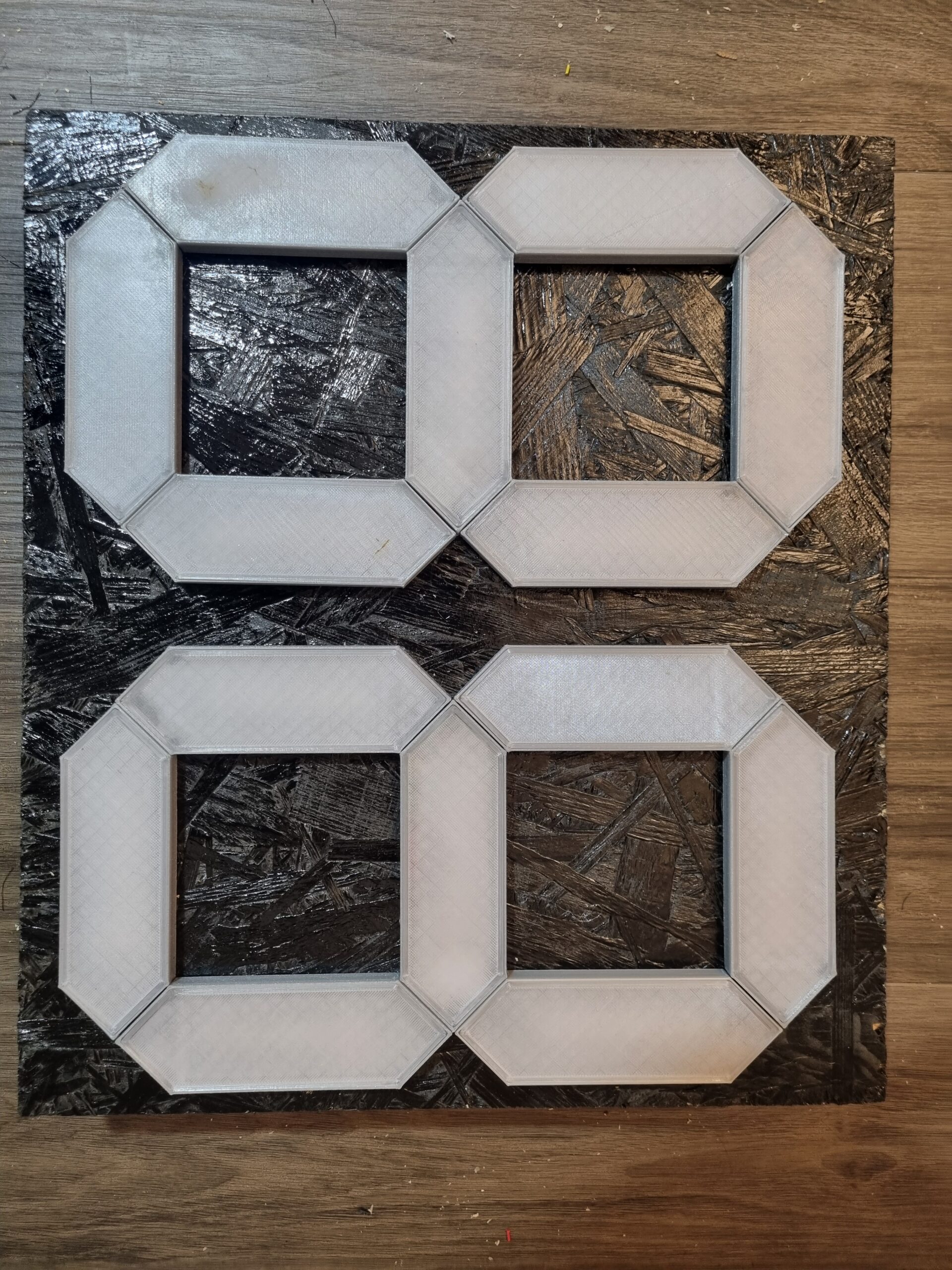
The case was printed with PLA filament on a 3D printer, other materials are also possible. 0.5 mm² stranded wires were used for the wiring of the control unit and the LED strips. Connections in the control unit were soldered or realised with a Wago terminal. The external cabling was realised with sturdy GX12 connectors. The 14 RGB elements containing a strip of 10 LEDs each were connected via crimped 2.54 mm Du-Pont connectors. The printed PLA shells and transparent covers of the two 7-segment elements were hot-glued onto a wooden plate. Power is supplied via a separate USB-C socket.
- Arduino Nano Controller Board (x1) (ORIGINAL) (CLONE)
- GX12 (1x 3-pin, 1x 4-pin, 1x 2-pin)
- Pressure Sensor (0 – 1.2 MPa, 1/4″, 5V)
- Condenser 16 V 1000 F (x1)
- USB-C Socket (x1)
- DuPont Connectors (Set)
- Wireclamps 5er (x2) (ORIGINAL) (CLONE)
- M3x8 Flatheadscrews (x4)
- M3 Nuts (x4)
- Wires 0.5 mm²
- Wooden plate
- Pressuresensor for calibration
Circuit
Software
- Autodesk Inventor Professional 2024 (Build: 209, Release: 2024.1 (06/29/2023))
- Fritzing beta (Ver. 0.9.4 )
- Arduino IDE 2.2.1
Libraries
- Adafruit_NeoPixel.h
- InterpolationLib.h
- string.h
- stdio.h
- Wire.h
Code
// A basic everyday NeoPixel strip test program.

// NEOPIXEL BEST PRACTICES for most reliable operation:
// - Add 1000 uF CAPACITOR between NeoPixel strip's + and - connections.
// - MINIMIZE WIRING LENGTH between microcontroller board and first pixel.
// - NeoPixel strip's DATA-IN should pass through a 300-500 OHM RESISTOR.
// - AVOID connecting NeoPixels on a LIVE CIRCUIT. If you must, ALWAYS
//   connect GROUND (-) first, then +, then data.
// - When using a 3.3V microcontroller with a 5V-powered NeoPixel strip,
//   a LOGIC-LEVEL CONVERTER on the data line is STRONGLY RECOMMENDED.
// (Skipping these may work OK on your workbench but can fail in the field)

#include <Adafruit_NeoPixel.h>
#include "InterpolationLib.h"
#include <string.h>
#include <stdio.h>
#include "Wire.h" //allows communication over i2c devices

// Define Pressure-Sensor
const int pressureInput = A7; //select the analog input pin for the pressure transducer
const int pressureZero = 102.4; //analog reading of pressure transducer at 0psi
const int pressureMax = 921.6; //analog reading of pressure transducer at 100psi
const int pressuretransducermaxPSI = 100; //psi value of transducer being used
const int baudRate = 115200; //constant integer to set the baud rate for serial monitor
const int sensorreadDelay = 250; //constant integer to set the sensor read delay in milliseconds

float pressureValue = 0; //variable to store the value coming from the pressure transducer

// Define LED
// Which pin on the Arduino is connected to the NeoPixels?
#define LED_PIN    3

// How many NeoPixels are attached to the Arduino?
#define LED_COUNT 19*10

// overall brightness setting 0 - 255
#define BRIGHTNESS 255

// how many pixels per segment?
#define PIXELSPERSEGMENT 10

// Declare our NeoPixel strip object:
Adafruit_NeoPixel strip(LED_COUNT, LED_PIN, NEO_GRB + NEO_KHZ800);


uint32_t onColor = strip.Color(255,255,255);
uint32_t offColor = strip.Color(0,0,0);


// defines for automatic color changes (interpolated) with   calcColor(float val)
#define NUMCOLORS 3
double pressures[NUMCOLORS] = {3.0, 5.0, 7.0};
double colorsR[NUMCOLORS] = {255, 255,   0};
double colorsG[NUMCOLORS] = {  0, 255, 255};
double colorsB[NUMCOLORS] = {  0,   0,   0};


/* 7 Segment display Segment definition
 AAAA
F    B
F    B
F    B
 GGGG
E    C
E    C
E    C
 DDDD  DOT
*/
// define order of segments here
int segments[3][8] = {
                 // A   B   C   D   E   F   G  DOT
                  { 5,  6,  3,  2,  1,  4,  0, 19}, // X.xx
                  { 9,  8, 11, 12, 13, 10,  7, 19}, // x.Xx
                  {19, 19, 19, 19, 19, 19, 19, 19}  // x.xX
  };
int segmentVals [3][8] = {0};


const byte A = 1<<0;
const byte B = 1<<1;
const byte C = 1<<2;
const byte D = 1<<3;
const byte E = 1<<4;
const byte F = 1<<5;
const byte G = 1<<6;
const byte DOT = 1<<7;


byte calc7segment(char val) {
  switch (val) {
    case '0':
      return A | B | C | D | E | F;
    break;

    case '1':
      return B | C;
    break;

    case '2':
      return A | B | G | E | D;
    break;

    case '3':
      return A | B | G | C | D;
    break;

    case '4':
      return F | G | B | C;
    break;

    case '5':
      return A | F | G | C | D;
    break;

    case '6':
      return A | F | G | E | D | C;
    break;

    case '7':
      return A | B | C;
    break;

    case '8':
      return 0xff & ~DOT;
    break;

    case '9':
      return 0xff & ~DOT & ~E;
    break;

    default:
      return G;
    break;
  }
}

void calcColor(float val) {
  float r, g, b;

  // (uint8_t)

  r = Interpolation::Linear(pressures, colorsR, NUMCOLORS, val, true);
  g = Interpolation::Linear(pressures, colorsG, NUMCOLORS, val, true);
  b = Interpolation::Linear(pressures, colorsB, NUMCOLORS, val, true);


  Serial.print("R");
  Serial.print(r);
  Serial.print("G");
  Serial.print(g);
  Serial.print("B");
  Serial.println(b);

  onColor = strip.Color(r,g,b);
}

void calcSegmentVals(float val) {
  char str[10] = {0};
  char segChar[3];
//  byte segVals[3] = 0;
  int i;

  if (val <= 0) {
    strcpy(str, " 0.00");
  } else if (val >= 9.99) {
    strcpy(str, " 9.99");
  } else {
    dtostrf(val, 5, 2, str);
  }

  Serial.println(str);

  segChar[0] = str[1];
  segChar[1] = str[3];
  segChar[2] = str[4];

  for (i=0; i<3; i++) {
    byte segVal = calc7segment(segChar[i]);

    for(int j=0; j<7; j++) {
      segmentVals[i][j] = (segVal&(1<<j)) ? 1: 0;
    }
  }
}

void writeVal2strip() {

  for (int i=0; i<3; i++)
    for (int j=0; j<7; j++)
      for (int k=0; k<PIXELSPERSEGMENT; k++)
        strip.setPixelColor(segments[i][j]*PIXELSPERSEGMENT+k, (segmentVals[i][j] != 0) ? onColor : offColor);

  strip.show();
}

void setup() {

  Serial.begin(115200);

  strip.begin();           // INITIALIZE NeoPixel strip object (REQUIRED)
  strip.show();            // Turn OFF all pixels ASAP
  strip.setBrightness(BRIGHTNESS); // Set BRIGHTNESS to about 1/5 (max = 255)


  colorWipe(strip.Color(255,   0,   0), 0); // Red

  colorWipe(strip.Color(0,   0,   0), 0); // black

}

void loop() {

  // Read Pressure Sensor

  pressureValue = analogRead(pressureInput); //reads value from input pin and assigns to variable
//  pressureValue = (((pressureValue-pressureZero)*pressuretransducermaxPSI)/(pressureMax-pressureZero))*0.0689476*2; //conversion equation to convert analog reading to psi
  pressureValue = (((analogRead(pressureInput)-95.956)/57.075)-0.6816)/1.4218;
  Serial.print(pressureValue, 1); //prints value from previous line to serial
  Serial.println(" Bar"); //prints label to serial
  delay(sensorreadDelay); //delay in milliseconds between read values
  delay(1000);

// OUTPUT VALUES ON LEDS

// OUTPUT TEST VALUES WITHOUT SENSOR
//
//  for (float val=0; val<10; val+=0.1) {
//
//  Serial.print(val);
//  Serial.print("   ");
//  calcColor(val);
//  calcSegmentVals(val);
//  writeVal2strip();
//  delay(200);
// }

// OUTPUT SENSOR VALUES
calcColor(pressureValue);
calcSegmentVals(pressureValue);
writeVal2strip();

}


// Some functions of our own for creating animated effects -----------------

// Fill strip pixels one after another with a color. Strip is NOT cleared
// first; anything there will be covered pixel by pixel. Pass in color
// (as a single 'packed' 32-bit value, which you can get by calling
// strip.Color(red, green, blue) as shown in the loop() function above),
// and a delay time (in milliseconds) between pixels.
void colorWipe(uint32_t color, int wait) {
  for(int i=0; i<strip.numPixels(); i++) { // For each pixel in strip...
    strip.setPixelColor(i, color);         //  Set pixel's color (in RAM)
    strip.show();                          //  Update strip to match
    delay(wait);                           //  Pause for a moment
  }
}

// Theater-marquee-style chasing lights. Pass in a color (32-bit value,
// a la strip.Color(r,g,b) as mentioned above), and a delay time (in ms)
// between frames.
void theaterChase(uint32_t color, int wait) {
  for(int a=0; a<10; a++) {  // Repeat 10 times...
    for(int b=0; b<3; b++) { //  'b' counts from 0 to 2...
      strip.clear();         //   Set all pixels in RAM to 0 (off)
      // 'c' counts up from 'b' to end of strip in steps of 3...
      for(int c=b; c<strip.numPixels(); c += 3) {
        strip.setPixelColor(c, color); // Set pixel 'c' to value 'color'
      }
      strip.show(); // Update strip with new contents
      delay(wait);  // Pause for a moment
    }
  }
}

// Rainbow cycle along whole strip. Pass delay time (in ms) between frames.
void rainbow(int wait) {
  // Hue of first pixel runs 5 complete loops through the color wheel.
  // Color wheel has a range of 65536 but it's OK if we roll over, so
  // just count from 0 to 5*65536. Adding 256 to firstPixelHue each time
  // means we'll make 5*65536/256 = 1280 passes through this outer loop:
  for(long firstPixelHue = 0; firstPixelHue < 5*65536; firstPixelHue += 256) {
    for(int i=0; i<strip.numPixels(); i++) { // For each pixel in strip...
      // Offset pixel hue by an amount to make one full revolution of the
      // color wheel (range of 65536) along the length of the strip
      // (strip.numPixels() steps):
      int pixelHue = firstPixelHue + (i * 65536L / strip.numPixels());
      // strip.ColorHSV() can take 1 or 3 arguments: a hue (0 to 65535) or
      // optionally add saturation and value (brightness) (each 0 to 255).
      // Here we're using just the single-argument hue variant. The result
      // is passed through strip.gamma32() to provide 'truer' colors
      // before assigning to each pixel:
      strip.setPixelColor(i, strip.gamma32(strip.ColorHSV(pixelHue)));
    }
    strip.show(); // Update strip with new contents
    delay(wait);  // Pause for a moment
  }
}

// Rainbow-enhanced theater marquee. Pass delay time (in ms) between frames.
void theaterChaseRainbow(int wait) {
  int firstPixelHue = 0;     // First pixel starts at red (hue 0)
  for(int a=0; a<30; a++) {  // Repeat 30 times...
    for(int b=0; b<3; b++) { //  'b' counts from 0 to 2...
      strip.clear();         //   Set all pixels in RAM to 0 (off)
      // 'c' counts up from 'b' to end of strip in increments of 3...
      for(int c=b; c<strip.numPixels(); c += 3) {
        // hue of pixel 'c' is offset by an amount to make one full
        // revolution of the color wheel (range 65536) along the length
        // of the strip (strip.numPixels() steps):
        int      hue   = firstPixelHue + c * 65536L / strip.numPixels();
        uint32_t color = strip.gamma32(strip.ColorHSV(hue)); // hue -> RGB
        strip.setPixelColor(c, color); // Set pixel 'c' to value 'color'
      }
      strip.show();                // Update strip with new contents
      delay(wait);                 // Pause for a moment
      firstPixelHue += 65536 / 90; // One cycle of color wheel over 90 frames
    }
  }
}
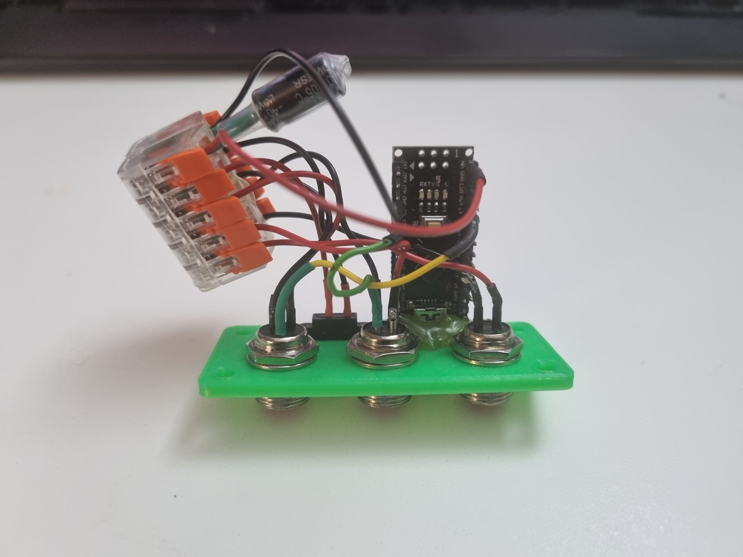
Hardware
The sensor was connected to a pressure reducer for the initial setup in order to calibrate it. This was done by reading out the sensor value via the serial monitor of the Arduino IDE for different values. A calibration line could then be created and the result output with the corresponding conversion factor in bar or psi.
Results
The 2×7-segment pressure indicator consists of two basic units. One is the control unit. This contains the Arduino Nano, a power distributor and the connections for the pressure sensor and the LED panels. The second unit is the segment display itself. RGB LED strips were glued into 3D printed housings, connected to each other and covered with transparent layers that were also printed. Each 7-segment element is supplied separately with 5 VDC. The control signal is forwarded to the second segment at the end of the first seven segments. An external power supply (not via the Arduino) is required to provide the LED strips with the necessary current. The USB connection of the Arduino nevertheless remains available as a diagnostic interface.

Outlook
The display works, but there are points that you should bear in mind when replicating it.
The 7 segments should not be connected with connectors, but the LED strips should be soldered together directly. The plug connections often resulted in cable breaks and the effort required to establish the crimp connections was time and material consuming. The intended modularity is not necessary, so we highly recommend soldering.
The solution of GX12 plugs is also not necessary. However, we were aiming for a solid solution that would withstand everyday workshop use. The use of connections with different numbers of pins also makes the setup foolproof.
Currently, a value of 7.2 bar, for example, is shown on the display as 72 kPa. The code already includes the option of integrating a separator between the two numerical elements in order to output the value in bar. We were not bothered by the fact that the value is displayed as kPa.
We are aiming with the idea of replacing the pressure sensor with a higher quality version, as the displayed values do not always correspond 100% with our analogue displays.
Reminder: In our case, 10 RGB LEDs were used per segment. If there is a deviation, the code must be adapted accordingly.