

Zusammenfassung
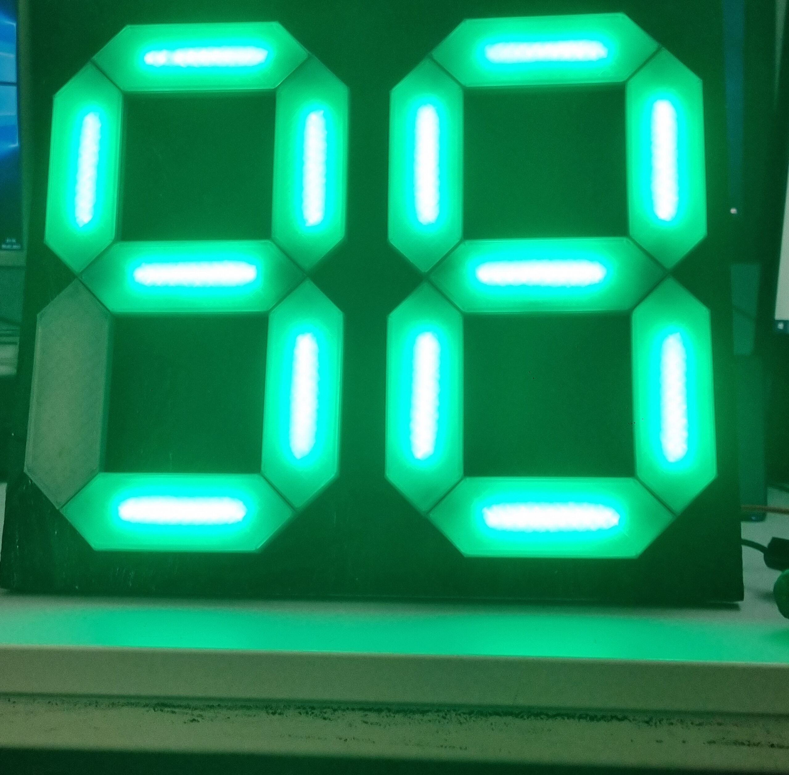
In welcher Werkstatt findet man keinen Druckluftkompressor? Vom Schlagschrauber über den Exzenterschleifer bis hin zum Druckluftmeißel kann die potenzielle Energie von Druckluft in vielfältiger Weise eingesetzt werden. Üblicherweise arbeiten handelsübliche Kompressoren mit einem Vorratsdruck von 8 bis 12 Bar. Wenn dem Kessel zu schnell zu viel Luft entzogen wird, kann der Vorratsdruck unter 5 Bar fallen. Doch wie kann ich aktuell den verfügbaren Druck herausfinden? Kleine Manometer an den Druckluftanschlüssen können darüber Auskunft geben, diese sind jedoch bereits aus ein paar Metern Entfernung schwer ablesbar. Aus diesem Grund wurde eine große digitale 2×7-Segmentanzeige gebaut, die den Druckluftwert anzeigt. Diese Anzeige ist von jedem Punkt in der Werkstatt gut sichtbar und zeigt neben der numerischen Anzeige auch durch einen RGB-Farbwechsel von Rot nach Grün den aktuellen Druckvorrat an. Die Steuerung erfolgt über einen Arduino Nano mit ATMega328 Mikrocontroller. Für den Bau werden neben einem 3D-Drucker transparentes Filament und ein entsprechender Drucksensor benötigt. Die Materialkosten belaufen sich bei diesem Projekt auf ca. 60 €.
Materialien & Methoden
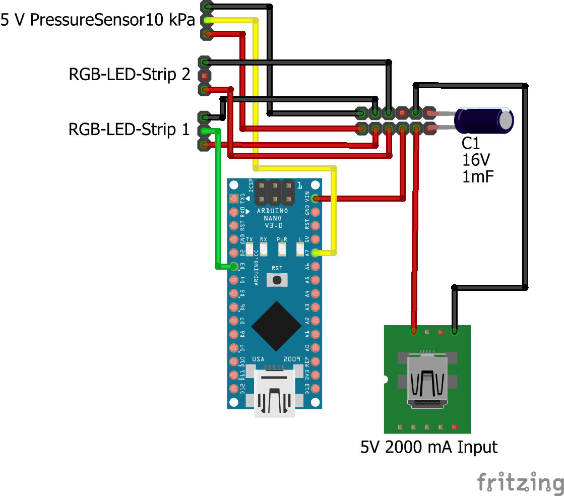
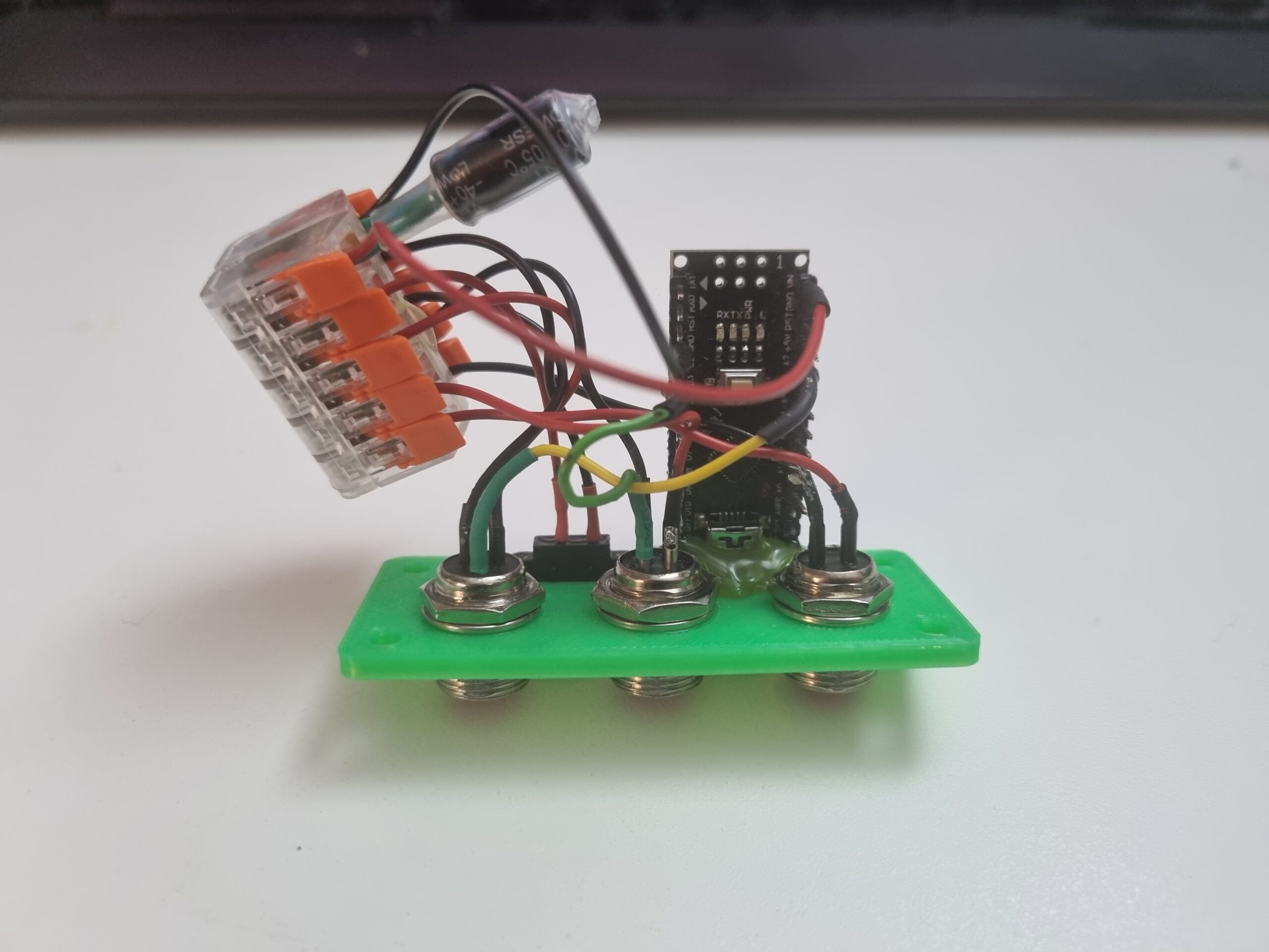
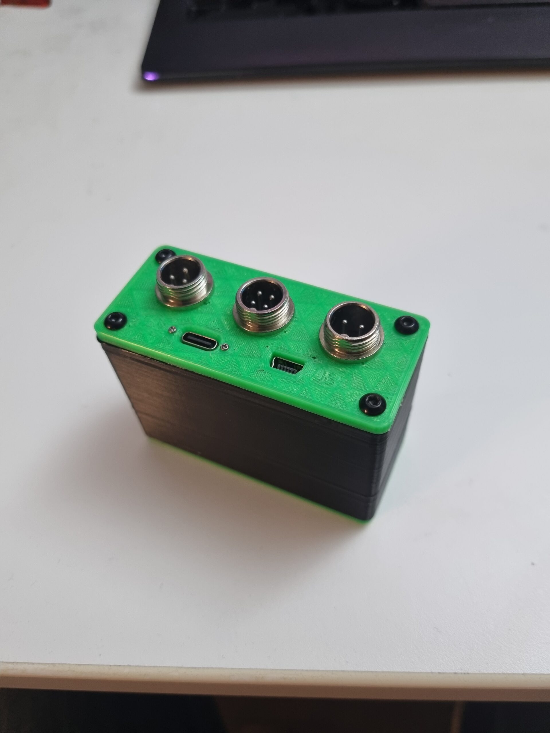
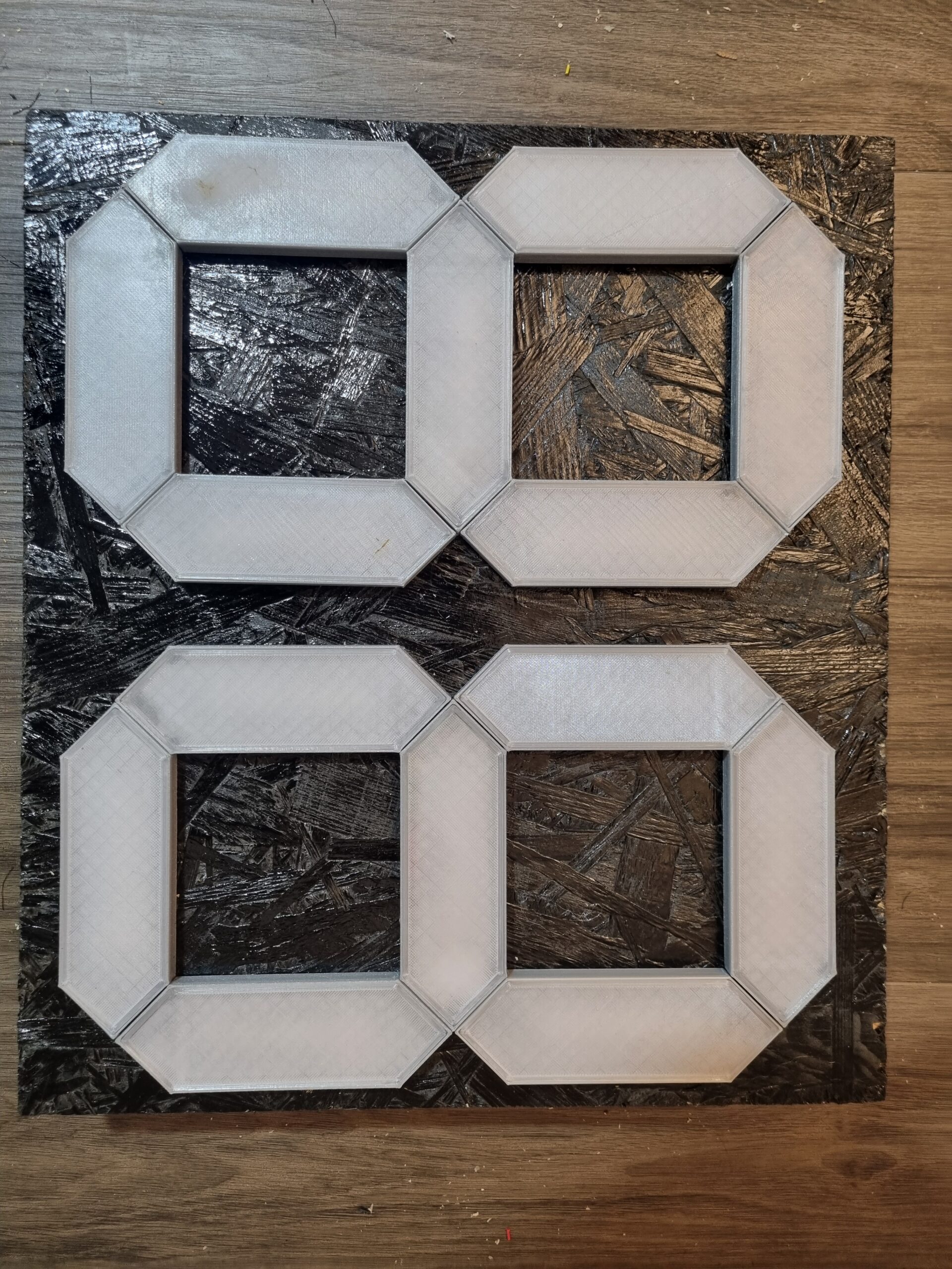
Alle Gehäuseteile wurden mit PLA-Filament auf einem 3D-Drucker gedruckt, andere Materialien sind auch möglich. 0.5 mm² Litzen wurden für die Verdrahtung des Steuergeräts und der LED Streifen verwendet. Verbindungen im Steuergerät wurden verlötet bzw. mit einer Wago-Klemme realisiert. Die Externe Verkabelung wurde mit GX12 Steckern umgesetzt. Die 14 RGB-Elemente wurden über gecrimpte 2.54 mm Du-Pont Steckverbindungen verbunden. Die gedruckten PLA-Schalen und transparenten Abdeckungen der beiden 7-Segment-Elemente wurden auf einer Holzplatte verschraubt. Die Stromversorgung erfolgt über eine separate USB-C-Buchse.
Komponenten
- Arduino Nano Controller Board (x1) (ORIGINAL) (KLON)
- GX12 Stecker (1x 3-polig, 1x 4-Polig, 1x 2-polig)
- Drucksensor (0 – 1.2 MPa, 1/4″, 5V)
- Kondensator 16 V 1000 F (x1)
- USB-C Buchse (x1)
- DuPont Stecker (Set)
- Kabelklemmen 5er (x2) (ORIGINAL) (KLON)
- M3x8 Linsenkopfschrauben (x4)
- M3 Muttern (x4)
- Litzenkabel 0.5 mm²
- Holzplatte
- Druckminderer zur Kalibrierung
Schaltplan
Software
- Autodesk Inventor Professional 2024 (Build: 209, Release: 2024.1 (06/29/2023))
- Fritzing beta (Ver. 0.9.4 )
- Arduino IDE 2.2.1
Bibliothekenverwaltung
- Adafruit_NeoPixel.h
- InterpolationLib.h
- string.h
- stdio.h
- Wire.h
Code
// A basic everyday NeoPixel strip test program.

// NEOPIXEL BEST PRACTICES for most reliable operation:
// - Add 1000 uF CAPACITOR between NeoPixel strip's + and - connections.
// - MINIMIZE WIRING LENGTH between microcontroller board and first pixel.
// - NeoPixel strip's DATA-IN should pass through a 300-500 OHM RESISTOR.
// - AVOID connecting NeoPixels on a LIVE CIRCUIT. If you must, ALWAYS
//   connect GROUND (-) first, then +, then data.
// - When using a 3.3V microcontroller with a 5V-powered NeoPixel strip,
//   a LOGIC-LEVEL CONVERTER on the data line is STRONGLY RECOMMENDED.
// (Skipping these may work OK on your workbench but can fail in the field)

#include <Adafruit_NeoPixel.h>
#include "InterpolationLib.h"
#include <string.h>
#include <stdio.h>
#include "Wire.h" //allows communication over i2c devices

// Define Pressure-Sensor
const int pressureInput = A7; //select the analog input pin for the pressure transducer
const int pressureZero = 102.4; //analog reading of pressure transducer at 0psi
const int pressureMax = 921.6; //analog reading of pressure transducer at 100psi
const int pressuretransducermaxPSI = 100; //psi value of transducer being used
const int baudRate = 115200; //constant integer to set the baud rate for serial monitor
const int sensorreadDelay = 250; //constant integer to set the sensor read delay in milliseconds

float pressureValue = 0; //variable to store the value coming from the pressure transducer

// Define LED
// Which pin on the Arduino is connected to the NeoPixels?
#define LED_PIN    3

// How many NeoPixels are attached to the Arduino?
#define LED_COUNT 19*10

// overall brightness setting 0 - 255
#define BRIGHTNESS 255

// how many pixels per segment?
#define PIXELSPERSEGMENT 10

// Declare our NeoPixel strip object:
Adafruit_NeoPixel strip(LED_COUNT, LED_PIN, NEO_GRB + NEO_KHZ800);


uint32_t onColor = strip.Color(255,255,255);
uint32_t offColor = strip.Color(0,0,0);


// defines for automatic color changes (interpolated) with   calcColor(float val)
#define NUMCOLORS 3
double pressures[NUMCOLORS] = {3.0, 5.0, 7.0};
double colorsR[NUMCOLORS] = {255, 255,   0};
double colorsG[NUMCOLORS] = {  0, 255, 255};
double colorsB[NUMCOLORS] = {  0,   0,   0};


/* 7 Segment display Segment definition
 AAAA
F    B
F    B
F    B
 GGGG
E    C
E    C
E    C
 DDDD  DOT
*/
// define order of segments here
int segments[3][8] = {
                 // A   B   C   D   E   F   G  DOT
                  { 5,  6,  3,  2,  1,  4,  0, 19}, // X.xx
                  { 9,  8, 11, 12, 13, 10,  7, 19}, // x.Xx
                  {19, 19, 19, 19, 19, 19, 19, 19}  // x.xX
  };
int segmentVals [3][8] = {0};


const byte A = 1<<0;
const byte B = 1<<1;
const byte C = 1<<2;
const byte D = 1<<3;
const byte E = 1<<4;
const byte F = 1<<5;
const byte G = 1<<6;
const byte DOT = 1<<7;


byte calc7segment(char val) {
  switch (val) {
    case '0':
      return A | B | C | D | E | F;
    break;

    case '1':
      return B | C;
    break;

    case '2':
      return A | B | G | E | D;
    break;

    case '3':
      return A | B | G | C | D;
    break;

    case '4':
      return F | G | B | C;
    break;

    case '5':
      return A | F | G | C | D;
    break;

    case '6':
      return A | F | G | E | D | C;
    break;

    case '7':
      return A | B | C;
    break;

    case '8':
      return 0xff & ~DOT;
    break;

    case '9':
      return 0xff & ~DOT & ~E;
    break;

    default:
      return G;
    break;
  }
}

void calcColor(float val) {
  float r, g, b;

  // (uint8_t)

  r = Interpolation::Linear(pressures, colorsR, NUMCOLORS, val, true);
  g = Interpolation::Linear(pressures, colorsG, NUMCOLORS, val, true);
  b = Interpolation::Linear(pressures, colorsB, NUMCOLORS, val, true);


  Serial.print("R");
  Serial.print(r);
  Serial.print("G");
  Serial.print(g);
  Serial.print("B");
  Serial.println(b);

  onColor = strip.Color(r,g,b);
}

void calcSegmentVals(float val) {
  char str[10] = {0};
  char segChar[3];
//  byte segVals[3] = 0;
  int i;

  if (val <= 0) {
    strcpy(str, " 0.00");
  } else if (val >= 9.99) {
    strcpy(str, " 9.99");
  } else {
    dtostrf(val, 5, 2, str);
  }

  Serial.println(str);

  segChar[0] = str[1];
  segChar[1] = str[3];
  segChar[2] = str[4];

  for (i=0; i<3; i++) {
    byte segVal = calc7segment(segChar[i]);

    for(int j=0; j<7; j++) {
      segmentVals[i][j] = (segVal&(1<<j)) ? 1: 0;
    }
  }
}

void writeVal2strip() {

  for (int i=0; i<3; i++)
    for (int j=0; j<7; j++)
      for (int k=0; k<PIXELSPERSEGMENT; k++)
        strip.setPixelColor(segments[i][j]*PIXELSPERSEGMENT+k, (segmentVals[i][j] != 0) ? onColor : offColor);

  strip.show();
}

void setup() {

  Serial.begin(115200);

  strip.begin();           // INITIALIZE NeoPixel strip object (REQUIRED)
  strip.show();            // Turn OFF all pixels ASAP
  strip.setBrightness(BRIGHTNESS); // Set BRIGHTNESS to about 1/5 (max = 255)


  colorWipe(strip.Color(255,   0,   0), 0); // Red

  colorWipe(strip.Color(0,   0,   0), 0); // black

}

void loop() {

  // Read Pressure Sensor

  pressureValue = analogRead(pressureInput); //reads value from input pin and assigns to variable
//  pressureValue = (((pressureValue-pressureZero)*pressuretransducermaxPSI)/(pressureMax-pressureZero))*0.0689476*2; //conversion equation to convert analog reading to psi
  pressureValue = (((analogRead(pressureInput)-95.956)/57.075)-0.6816)/1.4218;
  Serial.print(pressureValue, 1); //prints value from previous line to serial
  Serial.println(" Bar"); //prints label to serial
  delay(sensorreadDelay); //delay in milliseconds between read values
  delay(1000);

// OUTPUT VALUES ON LEDS

// OUTPUT TEST VALUES WITHOUT SENSOR
//
//  for (float val=0; val<10; val+=0.1) {
//
//  Serial.print(val);
//  Serial.print("   ");
//  calcColor(val);
//  calcSegmentVals(val);
//  writeVal2strip();
//  delay(200);
// }

// OUTPUT SENSOR VALUES
calcColor(pressureValue);
calcSegmentVals(pressureValue);
writeVal2strip();

}


// Some functions of our own for creating animated effects -----------------

// Fill strip pixels one after another with a color. Strip is NOT cleared
// first; anything there will be covered pixel by pixel. Pass in color
// (as a single 'packed' 32-bit value, which you can get by calling
// strip.Color(red, green, blue) as shown in the loop() function above),
// and a delay time (in milliseconds) between pixels.
void colorWipe(uint32_t color, int wait) {
  for(int i=0; i<strip.numPixels(); i++) { // For each pixel in strip...
    strip.setPixelColor(i, color);         //  Set pixel's color (in RAM)
    strip.show();                          //  Update strip to match
    delay(wait);                           //  Pause for a moment
  }
}

// Theater-marquee-style chasing lights. Pass in a color (32-bit value,
// a la strip.Color(r,g,b) as mentioned above), and a delay time (in ms)
// between frames.
void theaterChase(uint32_t color, int wait) {
  for(int a=0; a<10; a++) {  // Repeat 10 times...
    for(int b=0; b<3; b++) { //  'b' counts from 0 to 2...
      strip.clear();         //   Set all pixels in RAM to 0 (off)
      // 'c' counts up from 'b' to end of strip in steps of 3...
      for(int c=b; c<strip.numPixels(); c += 3) {
        strip.setPixelColor(c, color); // Set pixel 'c' to value 'color'
      }
      strip.show(); // Update strip with new contents
      delay(wait);  // Pause for a moment
    }
  }
}

// Rainbow cycle along whole strip. Pass delay time (in ms) between frames.
void rainbow(int wait) {
  // Hue of first pixel runs 5 complete loops through the color wheel.
  // Color wheel has a range of 65536 but it's OK if we roll over, so
  // just count from 0 to 5*65536. Adding 256 to firstPixelHue each time
  // means we'll make 5*65536/256 = 1280 passes through this outer loop:
  for(long firstPixelHue = 0; firstPixelHue < 5*65536; firstPixelHue += 256) {
    for(int i=0; i<strip.numPixels(); i++) { // For each pixel in strip...
      // Offset pixel hue by an amount to make one full revolution of the
      // color wheel (range of 65536) along the length of the strip
      // (strip.numPixels() steps):
      int pixelHue = firstPixelHue + (i * 65536L / strip.numPixels());
      // strip.ColorHSV() can take 1 or 3 arguments: a hue (0 to 65535) or
      // optionally add saturation and value (brightness) (each 0 to 255).
      // Here we're using just the single-argument hue variant. The result
      // is passed through strip.gamma32() to provide 'truer' colors
      // before assigning to each pixel:
      strip.setPixelColor(i, strip.gamma32(strip.ColorHSV(pixelHue)));
    }
    strip.show(); // Update strip with new contents
    delay(wait);  // Pause for a moment
  }
}

// Rainbow-enhanced theater marquee. Pass delay time (in ms) between frames.
void theaterChaseRainbow(int wait) {
  int firstPixelHue = 0;     // First pixel starts at red (hue 0)
  for(int a=0; a<30; a++) {  // Repeat 30 times...
    for(int b=0; b<3; b++) { //  'b' counts from 0 to 2...
      strip.clear();         //   Set all pixels in RAM to 0 (off)
      // 'c' counts up from 'b' to end of strip in increments of 3...
      for(int c=b; c<strip.numPixels(); c += 3) {
        // hue of pixel 'c' is offset by an amount to make one full
        // revolution of the color wheel (range 65536) along the length
        // of the strip (strip.numPixels() steps):
        int      hue   = firstPixelHue + c * 65536L / strip.numPixels();
        uint32_t color = strip.gamma32(strip.ColorHSV(hue)); // hue -> RGB
        strip.setPixelColor(c, color); // Set pixel 'c' to value 'color'
      }
      strip.show();                // Update strip with new contents
      delay(wait);                 // Pause for a moment
      firstPixelHue += 65536 / 90; // One cycle of color wheel over 90 frames
    }
  }
}
Hardware
Der Sensor wurde zum initialen Setup an einen Druckminderer angeschlossen, um ihn zu kalibrieren. Dies geschah, indem bei unterschiedlichen Werten der Sensorwert über den seriellen monitor der Arduino IDE ausgelesen wurde. Anschließend konnte eine Kalibriergerade erstellt werden und das Ergebnis mit entsprechendem Umrechnungsfaktor in Bar bzw. psi ausgegeben werden.
Ergebnisse
Die 2×7-Segment Druckanzeige besteht aus zwei Grundlegen Einheiten. Einerseits das Steuergerät. In diesem befinden sich der Arduino Nano, eine Spannungsverteilung und die Anschlüsse für den Drucksensor und die LED-Panels. Die zweite Einheit bildet die Segmentanzeige selbst. RGB-LED Streifen wurden in 3D gedruckte Gehäuse geklebt, miteinander verbunden und mit transparenten ebenfalls gedruckten Kunststoffabdeckungen verschlossen. Jedes 7-Segment-Element erhält separat 5 VDC. Das Steuersignal wird am Ende der ersten sieben Segmente zum zweiten weitergeleitet. Eine externe Stromversorgung (nicht über den Arduino) ist notwendig, um den LED-Streifen die notwendige Stromstärke zu Verfügung zu stellen. Der USB-Anschluss des Arduino bleibt dennoch als Diagnostikschnittstelle erhalten.

Ausblick
Die Anzeige erfüllt ihren Zweck, dennoch gibt es Punkte, die man bei einem Nachbau beachten sollte. Die 7 Segmente sollten nicht mit Steckern verbunden werden, sondern die LED-Streifen sollten direkt miteinander verlötet werden. Bei den Steckverbindungen kam es häufig zu Kabelbrüchen und der Aufwand zur Etablierung der Stecker war sehr hoch. Die beabsichtigte Modularität ist darüber hinaus nicht notwendig.
Die Lösung der Verkabelung über GX12-Stecker ist natürlich nicht erforderlich. Wir haben allerdings eine solide Lösung angestrebt, die auch im Werkstattalltag lange Zeit überlebt. Die Verwendung von Verbindungen mit unterschiedlicher Pinanzahl macht außerdem die Verkabelung idiotensicher.
Aktuell wird ein Wert von z.B. 7,2 Bar auf der Anzeige als 72 kPa ausgegeben. Der Code beinhaltet bereits die Möglichkeit ein Trennelement zwischen den beiden Ziffernelementen zu integrieren, um den Wert in Bar auszugeben. Uns hat es nicht weiter gestört, dass der Wert als kPa angezeigt wird.
Wir spielen mit dem Gedanken den Drucksensor gegen eine qualitativ hochwertigere Variante zu ersetzen, da die angezeigten Werte nicht immer 100% mit den analogen Anzeigen übereinstimmen.
Achtung: In unserem Fall wurden je Segment 10 RGB-LEDs verwendet. Bei einer Abweichung muss der Code entsprechend angepasst werden.