

Abstract
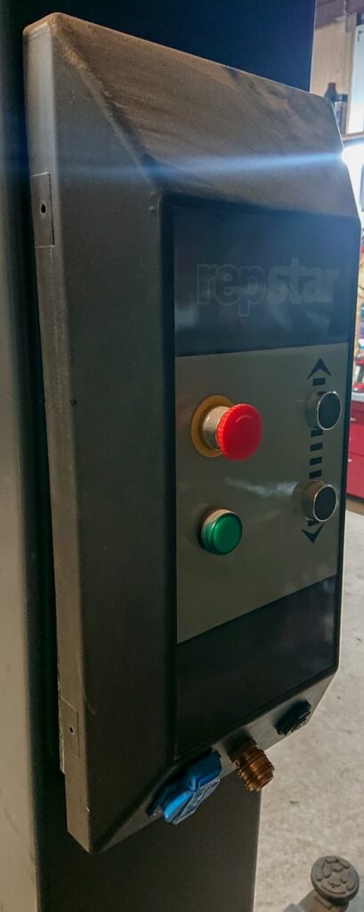
A remote control can make life easier. Especially if you work alone and without any assistance. In the hobby workshop, this may be the case more often. A vehicle lift is usually operated by a control on the lifting columns – it is not possible to operate the buttons and control the alignment on the vehicle at the same time, for example, when installing or removing the engine. In the following, a conventional vehicle lift was retrofitted with a radio remote control based on Arduino. The material costs amount to approx. $30, the installation is reliable and suitable for everyday use.
We initially developed a version based on radio communication (RC). In principle, this works perfectly, but there were interference frequencies in our workshop, so we finally decided on a more reliable Bluetooth variant (BT). Both approaches are shown here.
Introduction
The regular operation on a vehicle lift is as follows: The support arms are positioned under the vehicle’s lifting points and the lift is raised slightly. After checking again at the lifting points, the lift can be raised further. As soon as the wheels of the vehicle are free in the air, a final check of the pick-up points should be carried out before further lifting. This is the only way to ensure that the vehicle rests securely on the support arms and can be lifted further without falling off.
It can be tiresome to go back to the lifting column control unit after positioning or checking the support arms for lifting and then return to the vehicle multiple times. A remote control would be practical here, so that lifting can be done directly on the vehicle in one operation.
Another situation in which a remote control for the lifting platform appears to be useful is the installation or removal of engine or transmission units. Controlling the lift directly on site saves time and nerves, and exact positioning is easily possible without the assistance of a second person.
Surely there are already commercial products, but we wanted to take this project as an opportunity to create a solution that integrates perfectly into the daily workshop routine.
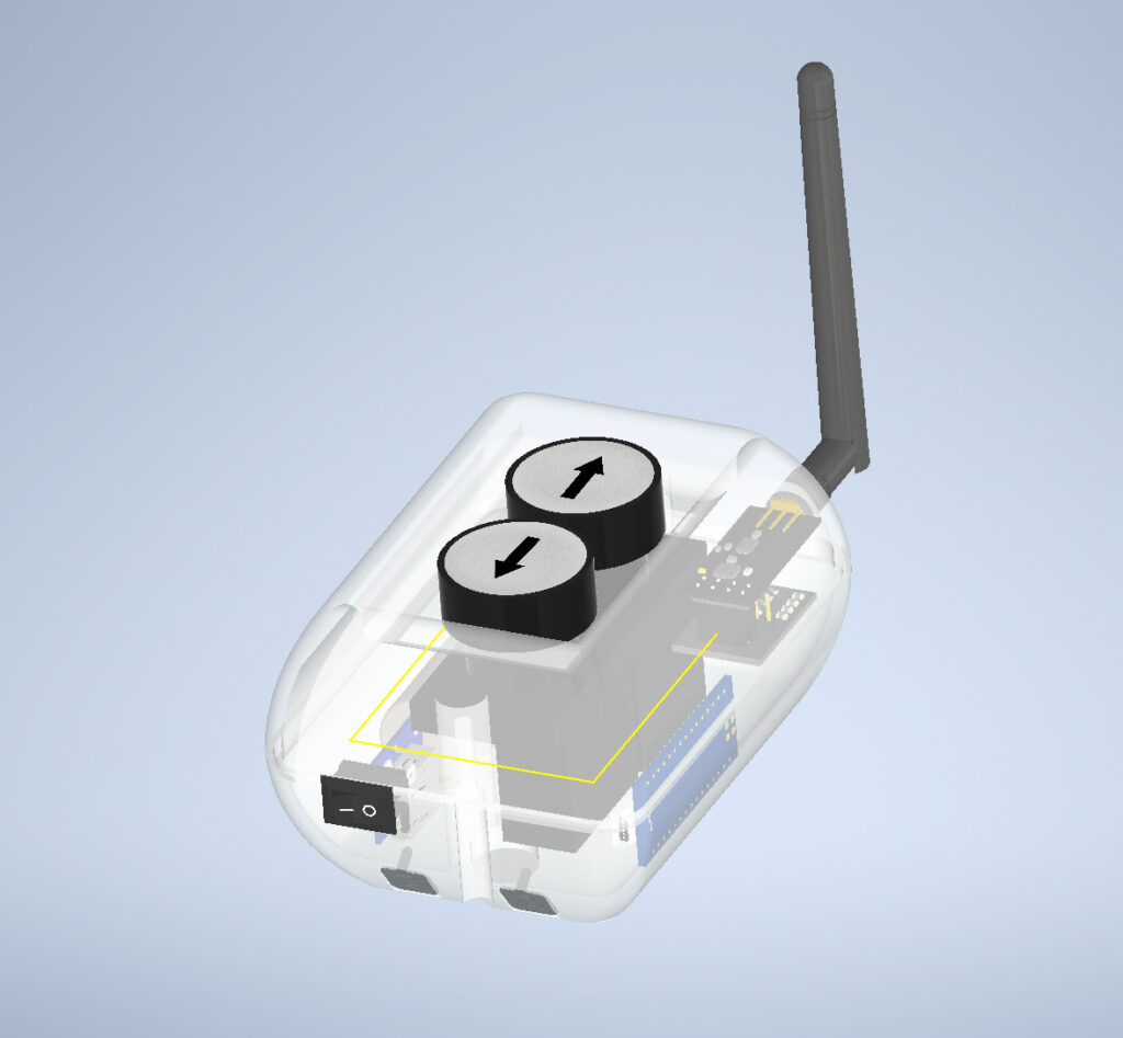
The plan was to use a transmitter unit as a remote control, which would have robust buttons and be able to withstand the rigors of everyday use in the workshop. The radio connection should be stable, reconnect automatically in the event of a connection loss. Obligatory battery operation should be integrated into the workflow without difficulty, which is why the holder also serves as a snap-in charging cradle.
Materials & Methods
All housing components were printed from PLA filament on a 3D printer. The electronic components inside the transmitter unit were soldered with 0.5 m² stranded cables. Crimped Dupont 2.64 mm connectors (also known as “Arduino cables”) were used as connectors for the receiver unit.
The source code was flashed onto the microprocessor via the USB interface.
Components
- Arduino Nano (x2) ($4 x 3 = $8)
- Relais 5V High trigger (x3) ($0.4 x 3 = $1.2)
- Momentary Switch White Arrow (x2) ($1.6 x 2 = $3.2)
- Step Down Converter ($0.5)
- 5 V Battery PCB TC4056A/TP4056 ($0.4)
- 3,7 V 18650 Li-Ion Battery ($3)
- Wago Clone 222-415 (x3) ($2)
- Battery Contacts AA (2 each type) ($1)
- Neodym Magnets (2-4) ($2)
RC-Version:
- NRF24L01 PA (Transmitter) ($2.5)
- DIP24L01 (Receiver) ($0.7)
- Expansion Board (x2) (2x $0.6 = $1.2)
BT-Version:
- Bluetooth-module HC-05 (Transmitter) ($3)
- Bluetooth-module HC-06 (Receiver) ($3)
- Or HC-05 (x2) for Transmitter & Receiver
Software
- Autodesk Inventor Professional 2019 (Build: 265, Release: 2019.2)
- Fritzing beta (Ver. 0.9.4 )
- Arduino IDE 1.8.10 (Board: Arduino Nano, Programmer: AVRISP mkII, Prozessor: ATmega328P (Old Bootloader))

Source Code
The buttons on the remote control send a specific signal to the receiver unit, which activate either the up or down relay. However, the “enable” relay is always activated, which moves the safety pins of the lifting platform so that movement is possible at all. For safety reasons, this relay is not bypassed, but is only activated when operation is desired. If the connection to the receiver unit fails, the relays switch off and the lift stops.
On the transmitter unit, two LEDs are controlled by code: the green LED indicates the general state of operation of the microcontroller. The red LED indicates the connection status with the receiver unit. If it is not illuminated, the connection is established and the unit is ready for use. If the red LED flashes quickly, no connection to the receiver can be established. During the keystroke on the transmitter, a continuous light in the length of the keystroke indicates the successful transmission of the signal.
The radio-controlled variant (RC) also contains a code section which, in the event of a faulty radio communication, periodically restarts the receiver module via the reset pin in order to attempt a new connection. To facilitate debugging of the connection, the code also contains messages that are transmitted and can be retrieved via the Serial Monitor.
Libraries
- RF24.h
- printf.h
- SPI.h
- SoftwareSerial.h
Code Transmitter (RC)
#include <SPI.h>
#include "printf.h"
#include "RF24.h"

#define TURNOFFDELAY 10000 /* in ms */

// Pins
#define LED_PIN_POWER 2
#define LED_PIN 3
#define BUTTONUP_PIN 5
#define BUTTONDOWN_PIN 6
#define CE_PIN 7
#define CSN_PIN 8

// Messages
#define UP    'U'
#define DOWN  'D'
#define STOP  'S'
#define R_PING  'I'
#define R_PONG  'O'

#define PIPE 0 //0x42216836aa

// instantiate an object for the nRF24L01 transceiver
RF24 radio(CE_PIN, CSN_PIN);

uint8_t address[][6] = {"1Node", "2Node"};
bool radioNumber = 1; // 0 uses address[0] to transmit, 1 uses address[1] to transmit
bool role = false;  // true = TX role, false = RX role

uint8_t message = STOP;

bool report = false,
    error = false;

unsigned long turnOffTime = 10000;

void setup() {
  pinMode(LED_PIN, OUTPUT);
  pinMode(LED_PIN_POWER, OUTPUT);
  pinMode(BUTTONUP_PIN, INPUT_PULLUP);
  pinMode(BUTTONDOWN_PIN, INPUT_PULLUP);
  digitalWrite(LED_PIN, false);


  while (!radio.begin()) { // radio is not responding
    for (int i = 0; i<5; i++) { // blink slowly for 5s
      digitalWrite(LED_PIN, true);
      delay(500);
      digitalWrite(LED_PIN, false);
      delay(500);
    }
  }

  // Set the PA Level low to try preventing power supply related problems
  // because these examples are likely run with nodes in close proximity to
  // each other.
  radio.setPALevel(RF24_PA_HIGH);  // RF24_PA_MAX is default. RF24_PA_LOW

  // save on transmission time by setting the radio to only transmit the
  // number of bytes we need to transmit a uint8_t
  radio.setPayloadSize(sizeof(message)); // uint8_t datatype occupies 1 byte

  // set the TX address of the RX node into the TX pipe
  radio.openWritingPipe(address[radioNumber]);     // always uses pipe 0

  // set the RX address of the TX node into a RX pipe
  radio.openReadingPipe(1, address[!radioNumber]); // using pipe 1

  radio.stopListening();  // put radio in TX mode

}

void loop() {
  bool buttonUp = !digitalRead(BUTTONUP_PIN);
  bool buttonDown = !digitalRead(BUTTONDOWN_PIN);
  digitalWrite(LED_PIN_POWER, HIGH);

  if (buttonUp == buttonDown == true){ // Error: Both Buttons Pressed
    message = STOP;
    error = true;
    digitalWrite(LED_PIN, false);
  } else if (buttonUp) {
    message = UP;
    digitalWrite(LED_PIN, true);
    turnOffTime = millis() + TURNOFFDELAY;
  } else if (buttonDown) {
    message = DOWN;
    digitalWrite(LED_PIN, true);
    turnOffTime = millis() + TURNOFFDELAY;
  } else if (buttonUp == buttonDown == false) {
    message = STOP;
    error = false;
    digitalWrite(LED_PIN, false);
  }

  report = radio.write(&message, sizeof(uint8_t));

  if (!report) {  // Transmission failed
    for (int i = 0; i<5; i++) { // blink fast for 0.5s
      digitalWrite(LED_PIN, true);
      delay(50);
      digitalWrite(LED_PIN, false);
      delay(50);
    }
  }
}
Code Transmitter (BT)
#include <SoftwareSerial.h>

// Pins
#define POWER_LED A2
#define LED_PIN A3
#define BUTTONUP_PIN 5
#define BUTTONDOWN_PIN 6
#define RXPIN 3
#define TXPIN 2
#define STATEPIN 4
#define ENABLEPIN A1

// Messages
#define UP    'U'
#define DOWN  'D'
#define STOP  'S'

#define HBBBLUETOOTHADDR 20:17:03:15:03:34
#define BINDSTR "AT+BIND=2017,03,150334"

SoftwareSerial blueSerial(RXPIN, TXPIN); // RX, TX

char message = STOP;

bool ledState = false;

void setup() {
  // intit pins
  pinMode(POWER_LED, OUTPUT);
  pinMode(LED_PIN, OUTPUT);
  pinMode(BUTTONUP_PIN, INPUT_PULLUP);
  pinMode(BUTTONDOWN_PIN, INPUT_PULLUP);
  pinMode(ENABLEPIN, OUTPUT);
  pinMode(STATEPIN, INPUT);

  digitalWrite(LED_PIN, false);
  digitalWrite(POWER_LED, true);
  digitalWrite(ENABLEPIN, true);

  Serial.begin(38400);
  while (!Serial) {
    // some boards need to wait to ensure access to serial over USB
  }

  // 9600

  Serial.println("Startup");

  if (false) { // configure bluetooth module
    blueSerial.begin(38400); //38400

    while (1) {

      if (Serial.available()>0)
        blueSerial.write(Serial.read());

      if (blueSerial.available()>0)
        Serial.write(blueSerial.read());
      }
    } else {
      blueSerial.begin(9600);
    }

} // setup

void loop() {
  bool buttonUp = !digitalRead(BUTTONUP_PIN);
  bool buttonDown = !digitalRead(BUTTONDOWN_PIN);

  bool statePin = digitalRead(STATEPIN);

  if (!statePin) {
    ledState = !ledState;

    digitalWrite(LED_PIN, ledState);

    Serial.println("Waiting for connection");
  } else {

    if (buttonUp == buttonDown == true){ // Error: Both Buttons Pressed
      message = STOP;
      digitalWrite(LED_PIN, false);
    } else if (buttonUp) {
      message = UP;
      digitalWrite(LED_PIN, true);
    } else if (buttonDown) {
      message = DOWN;
      digitalWrite(LED_PIN, true);
    } else if (buttonUp == buttonDown == false) {
      message = STOP;
      digitalWrite(LED_PIN, false);
    }

    Serial.print(statePin);
    Serial.print("Sending: ");
    Serial.write(message);
    Serial.println("\n");

    blueSerial.write(message);
  }

  delay(45);

} // loop
Code Receiver (RC)
#include <SPI.h>
#include "printf.h"
#include "RF24.h"

#define TRANSMISSIONTIMEOUT 100 /* in ms */
#define RESETTIMEOUT 1000       /* in ms */

// Pins
#define RESET_PIN 6
#define LED_PIN 2
#define RELAYUP_PIN 4
#define RELAYDOWN_PIN 5
#define RELAYENABLE_PIN 3
#define CE_PIN 7
#define CSN_PIN 8

// Messages
#define UP    'U'
#define DOWN  'D'
#define STOP  'S'
#define R_PING  'I'
#define R_PONG  'O'

#define PIPE 0 //0x42216836aa

// instantiate an object for the nRF24L01 transceiver
RF24 radio(CE_PIN, CSN_PIN);

uint8_t address[][6] = {"1Node", "2Node"};
bool radioNumber = 0; // 0 uses address[0] to transmit, 1 uses address[1] to transmit

uint8_t message = STOP;

uint8_t pipe = 0;

bool report = false,
    error = false;

unsigned long expectedTransmissionTime = 10000,
              resetTimeout = 100000;

void setup() {
  // intit pins
  pinMode(LED_PIN, OUTPUT);
  pinMode(RELAYUP_PIN, OUTPUT);
  pinMode(RELAYDOWN_PIN, OUTPUT);
  pinMode(RELAYENABLE_PIN, OUTPUT);
  digitalWrite(LED_PIN, false);
  digitalWrite(RELAYUP_PIN, false);
  digitalWrite(RELAYDOWN_PIN, false);
  digitalWrite(RELAYENABLE_PIN, false);

  while (!radio.begin()) { // radio is not responding
    for (int i = 0; i<5; i++) { // blink slowly for 5s
      digitalWrite(LED_PIN, true);
      delay(500);
      digitalWrite(LED_PIN, false);
      delay(500);
    }
  }

  // Set the PA Level low to try preventing power supply related problems
  // because these examples are likely run with nodes in close proximity to
  // each other.
  radio.setPALevel(RF24_PA_HIGH);  // RF24_PA_MAX is default. RF24_PA_LOW RF24_PA_LOW RF24_PA_MAX RF24_PA_MIN=0

  // save on transmission time by setting the radio to only transmit the
  // number of bytes we need to transmit a uint8_t
  radio.setPayloadSize(sizeof(message)); // uint8_t datatype occupies 1 byte

  // set the TX address of the RX node into the TX pipe
  radio.openWritingPipe(address[radioNumber]);     // always uses pipe 0

  // set the RX address of the TX node into a RX pipe
  radio.openReadingPipe(1, address[!radioNumber]); // using pipe 1

  radio.startListening();  // put radio in RX mode

}

void loop() {
  error = true;
  while(millis() < expectedTransmissionTime) {
    if (radio.available(&pipe)) {
      if (radio.getPayloadSize() > 1) {
        error = true;
        expectedTransmissionTime = millis() + TRANSMISSIONTIMEOUT;
        resetTimeout = millis() + RESETTIMEOUT;
        break;
      } else {
        radio.read(&message, 1);
        error = false;
        expectedTransmissionTime = millis() + TRANSMISSIONTIMEOUT;
        resetTimeout = millis() + RESETTIMEOUT;
        break;
      }
    }
  }

  if (millis() > resetTimeout) {
    pinMode(RESET_PIN, OUTPUT);
  }

  if (error) {
    digitalWrite(RELAYUP_PIN, false);
    digitalWrite(RELAYDOWN_PIN, false);
    digitalWrite(RELAYENABLE_PIN, false);
  } else {

    switch (message) {
      case UP:
        digitalWrite(RELAYUP_PIN, true);
        digitalWrite(RELAYDOWN_PIN, false);
        digitalWrite(RELAYENABLE_PIN, true);
      break;

      case DOWN:
        digitalWrite(RELAYUP_PIN, false);
        digitalWrite(RELAYDOWN_PIN, true);
        digitalWrite(RELAYENABLE_PIN, true);
      break;

      case STOP:
      default:
        digitalWrite(RELAYUP_PIN, false);
        digitalWrite(RELAYDOWN_PIN, false);
        digitalWrite(RELAYENABLE_PIN, false);
      break;
    }
  }
}
Code Receiver (BT)
#include <SoftwareSerial.h>

//
#define TRANSMISSIONTIMEOUT 100 /* in ms */
#define RESETTIMEOUT 2000

// Pins
#define LED_PIN A1
#define RELAYENABLE_PIN 7
#define RELAYUP_PIN 4
#define RELAYDOWN_PIN 5
#define RESET_PIN 6

// Messages
#define UP    'U'
#define DOWN  'D'
#define STOP  'S'


SoftwareSerial blueSerial(2, 3); // RX, TX

unsigned long expectedTransmissionTime = 10000,
              resetTime = 10000;

char message = 0;

void setup() {
    // intit pins
  pinMode(LED_PIN, OUTPUT);
  pinMode(RELAYUP_PIN, OUTPUT);
  pinMode(RELAYDOWN_PIN, OUTPUT);
  pinMode(RELAYENABLE_PIN, OUTPUT);
  digitalWrite(LED_PIN, false);
  digitalWrite(RELAYUP_PIN, false);
  digitalWrite(RELAYDOWN_PIN, false);
  digitalWrite(RELAYENABLE_PIN, false);

  Serial.begin(115200);
  while (!Serial) {
    // some boards need to wait to ensure access to serial over USB
  }

  blueSerial.begin(9600);

} // setup

void loop() {

  while(millis() < expectedTransmissionTime) {
    if (blueSerial.available()) {
      Serial.print(F("Received "));
      message = blueSerial.read();
      Serial.print(message);
      Serial.println("  .");
     resetTime = millis() + RESETTIMEOUT;
     break;
    }
  }

  if (millis() >= expectedTransmissionTime) {

    digitalWrite(RELAYUP_PIN, false);
    digitalWrite(RELAYDOWN_PIN, false);
    digitalWrite(RELAYENABLE_PIN, false);
    message = STOP;
  }

    switch (message) {
      case UP:
        digitalWrite(RELAYUP_PIN, true);
        digitalWrite(RELAYDOWN_PIN, false);
        digitalWrite(RELAYENABLE_PIN, true);
        expectedTransmissionTime = millis() + TRANSMISSIONTIMEOUT;
      break;

      case DOWN:
        digitalWrite(RELAYUP_PIN, false);
        digitalWrite(RELAYDOWN_PIN, true);
        digitalWrite(RELAYENABLE_PIN, true);
        expectedTransmissionTime = millis() + TRANSMISSIONTIMEOUT;
      break;

      case STOP:
        digitalWrite(RELAYUP_PIN, false);
        digitalWrite(RELAYDOWN_PIN, false);
        digitalWrite(RELAYENABLE_PIN, false);
        expectedTransmissionTime = millis() + TRANSMISSIONTIMEOUT;
      break;
  }
} // loop
Results
Receiver
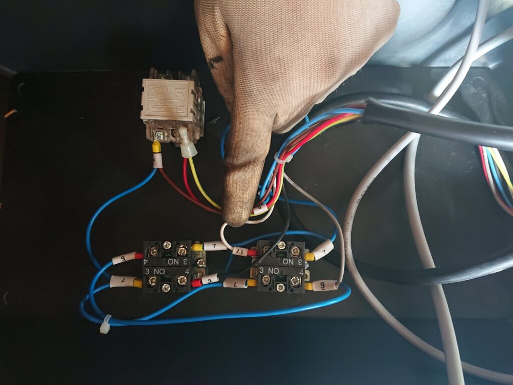
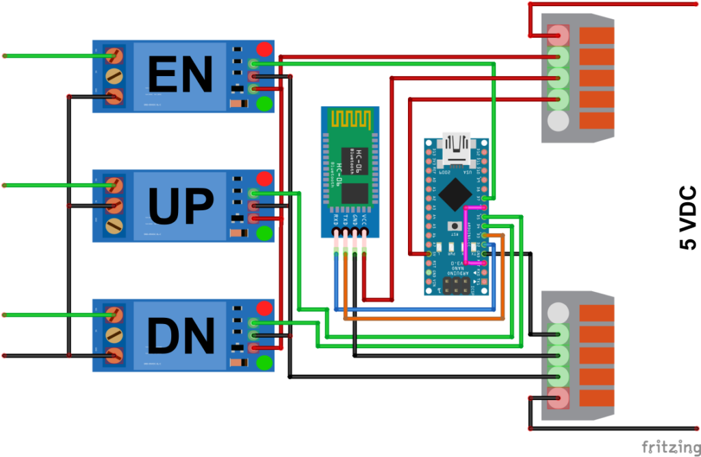
Three relays were used, which were connected in the control panel in parallel to the two existing pushbuttons. In addition to one relay each for up/down travel, a third relay passes on the enable signal and unlocks the lift’s safety mechanism. The relays operate with a high trigger, ensuring that if the signal connection to the remote control or the power supply to the transmitter unit is interrupted, there will be no unwanted movement of the lifting platform, thus ensuring safety. Together with an Arduino Nano and the NRF24L01 (RC) radio module or an HC-06 (BT) Bluetooth module, the receiver unit was connected to a 5 VDC distribution that is powered by the 12 VDC voltage of the lift using a step-down converter (not shown). It is important that the Arduino and its modules be powered by 5 VDC. If the lift does not supply 12 VDC, but perhaps only mains voltage (230 VAC), a power supply (~2 A) must be used.
Transmitter
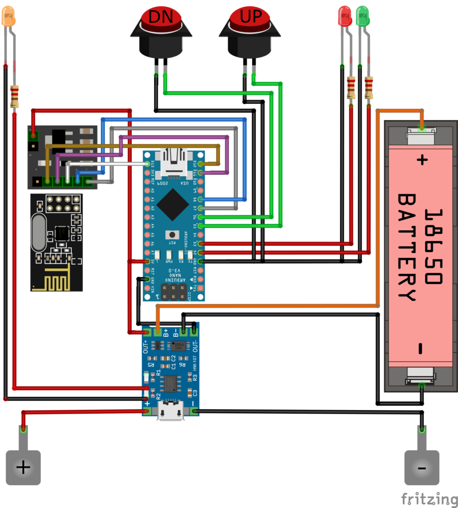
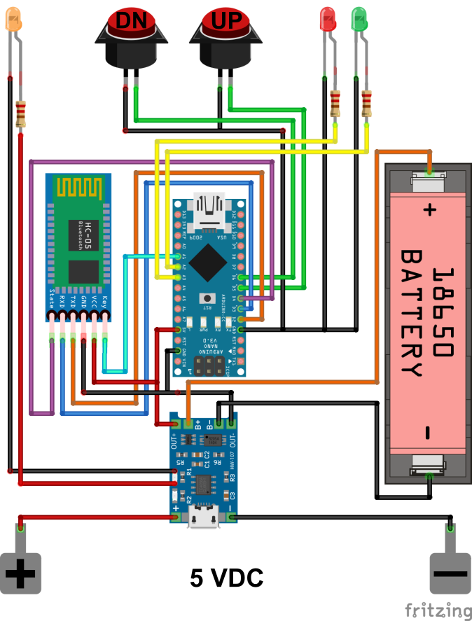
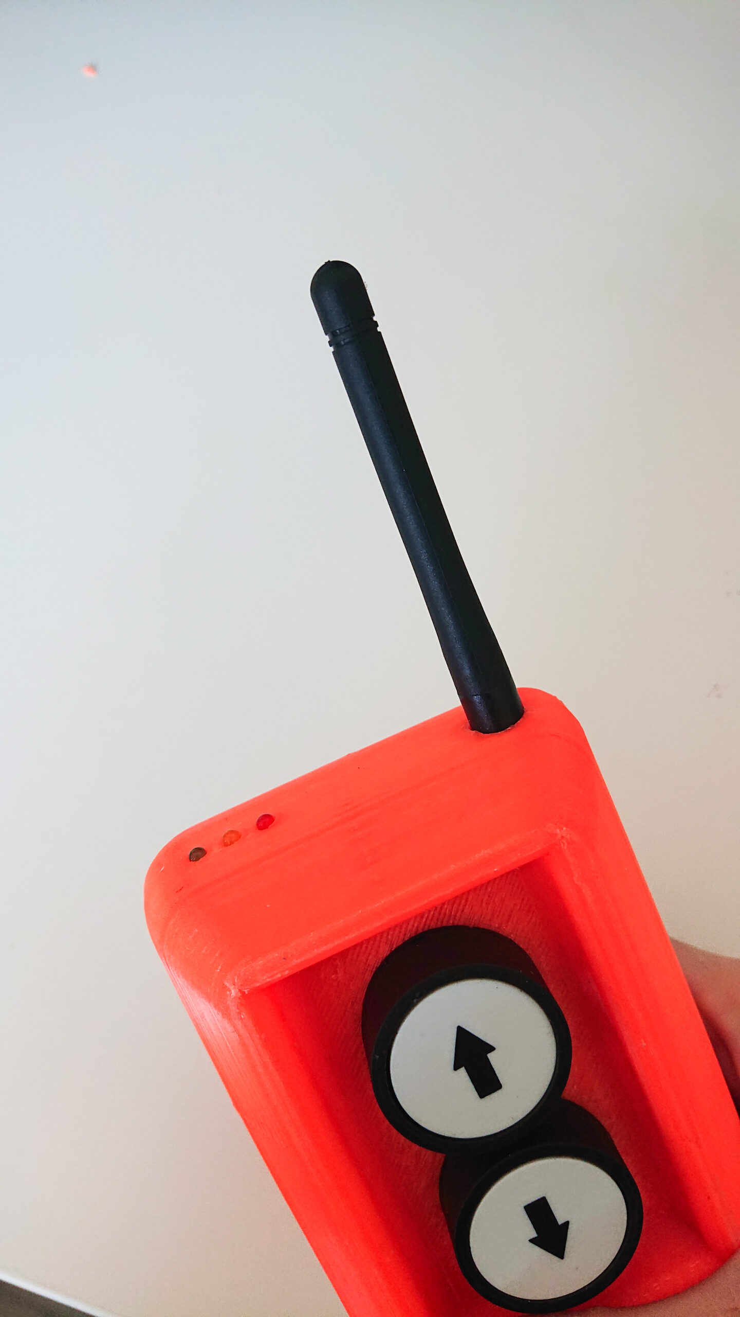
In addition to an Arduino Nano with a radio module (NRF24L01) or Bluetooth module (HC-05), the transmitter unit has solid buttons for everyday workshop use and a 3.7 V battery with 5 V charging mechanism that can guarantee simplicity and reliability – and last a long time.
LEDs for status indication complete the technology of the sending unit.
The green LED lights up as soon as the transmitter is switched on with the rocker switch and the Arduino is started.
The red LED informs about the status of the transmitter module: While the button to operate the lift is pressed, the red LED lights up to indicate that a signal is being transmitted to the receiver. If, on the other hand, the red LED flashes continuously, there is no connection to the receiver. In this case, the radio module periodically attempts to reconnect.
The yellow LED lights up as soon as the transmitter unit is positioned in the charging station and the battery is being charged. An ordinary power bank with a 3.7 V battery was used as battery and 5 V charge controller. Depending on the charging electronics used, the yellow LED lights up continuously or flashes and switches off when charging is complete.
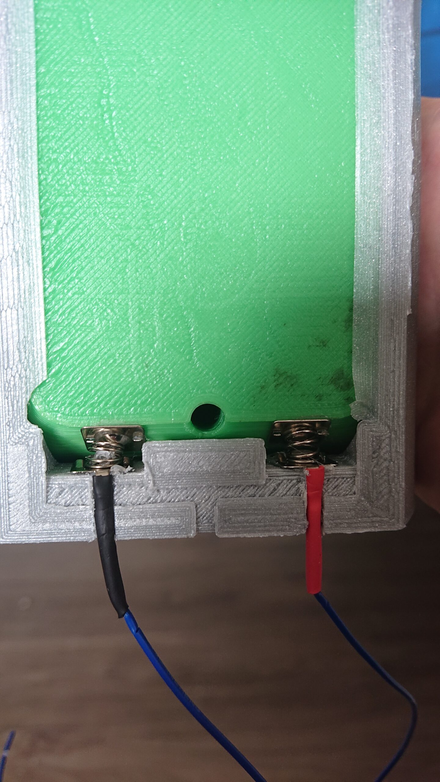
Contact plates for AA batteries were used to design the transmitter’s charging tray and attached with hot glue. The latching mechanism was adapted in CAD so that the remote control is automatically switched off when it is inserted into the charging cradle. Neodymium magnets in the back panel ensure that the transmitter adheres to metallic surfaces.


Discussion & Outlook
In this project, a standard vehicle lift was retrofitted with radio remote control. The installation was simple, the operation intuitive and reliable. No safety features were bypassed and operation does not pose any safety issues if carried out properly. By selecting one of the two methods (RC vs. Bluetooth), it is possible to implement a functional and reliable solution with the alternative radio protocol even under interfering frequencies (as is the case in the test workshop). However, by using the radio modules, a higher radio range is possible. Both implementations were presented, built and successfully tested. As an extension with regard to safety aspects, an emergency stop switch on the transmitter unit could be considered – but the presented system with high-trigger relays currently shows no necessity for this.