

Abstract
In this project, an ordinary video projector was controlled using serial commands (RS232) via an Arduino Mega. Operation through an external custom-made 3D printed multimedia panel fitting into a 50 mm cable channel eliminates the need for the proprietary infrared remote control. The cost of the equipment was reduced by 80% compared to a commercial solution and is highly customizable. The secondary objective of the installation was to provide the user with a simple, unambiguous control panel that is completely reliable. The project presented covers the entire work-through process from analysis and planning to installation and the finished result.
Introduction
General intention
If a presentation is planned, the technical problems are usually not long in coming. Be it incompatibilities with connection, missing remote control or missing audio. The possibility of events that may occur seems almost endless. And everyone knows these situations. Not every user has the necessary technical background knowledge to perform an error analysis. Add to this the stress of the lecturer and the chaos is perfect. A solution has been sought to avoid this element of frustration in the best possible way. Time delays can thus be reduced and a professional appearance of the lecturer is not jeopardized by the local, unpredictable technical infrastructure.
Yes, there are a lot of commercial products on the market that mostly work around the problems mentioned here. But these commercial systems are incredibly expensive compared to the simplicity with which such a system could be built.
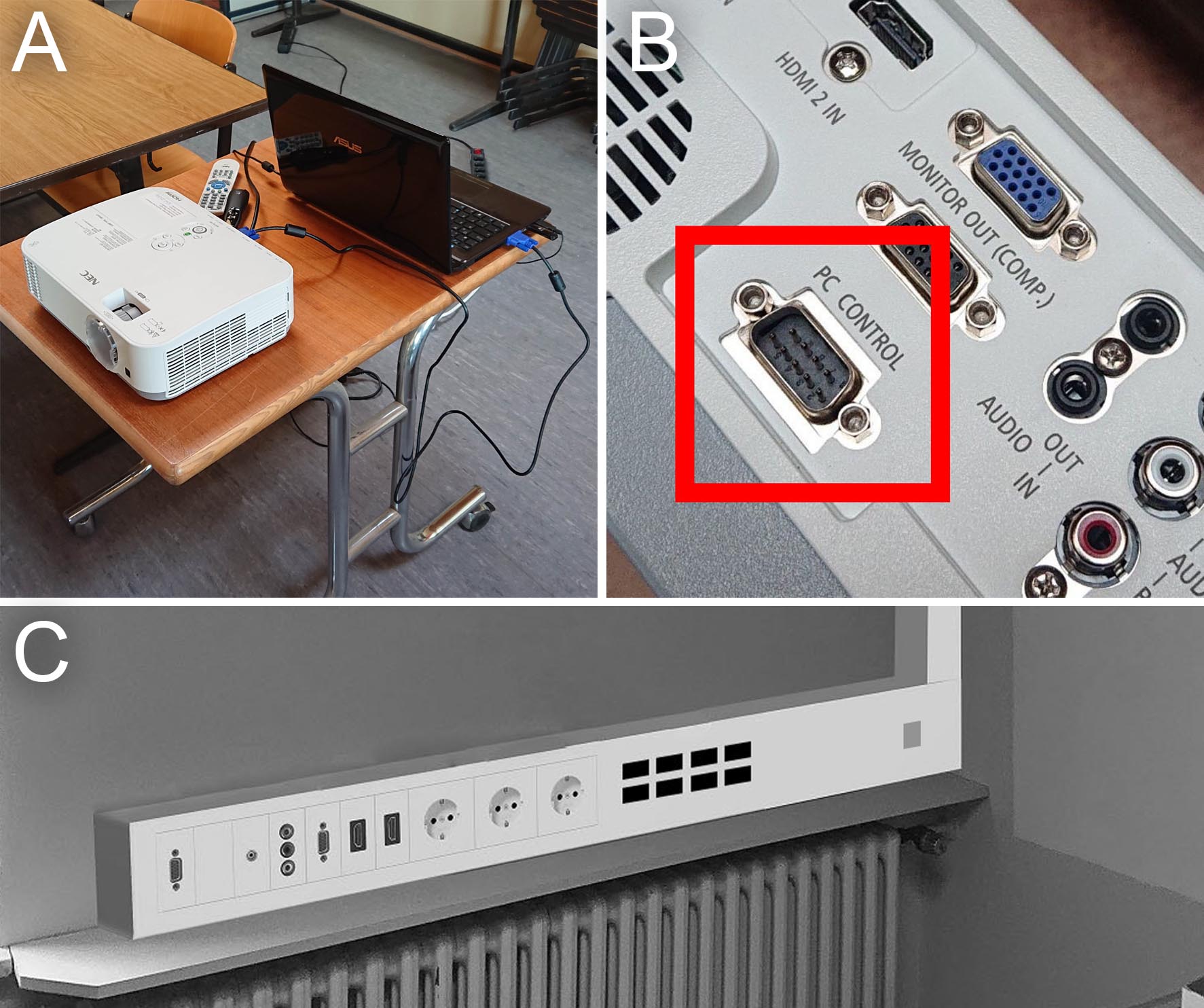
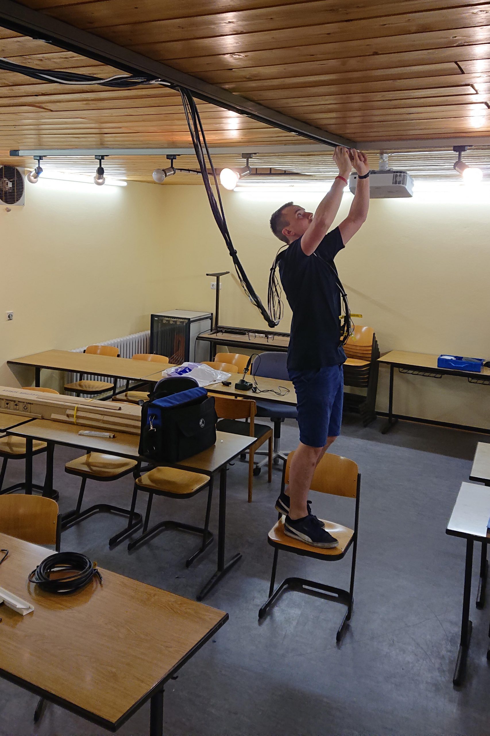
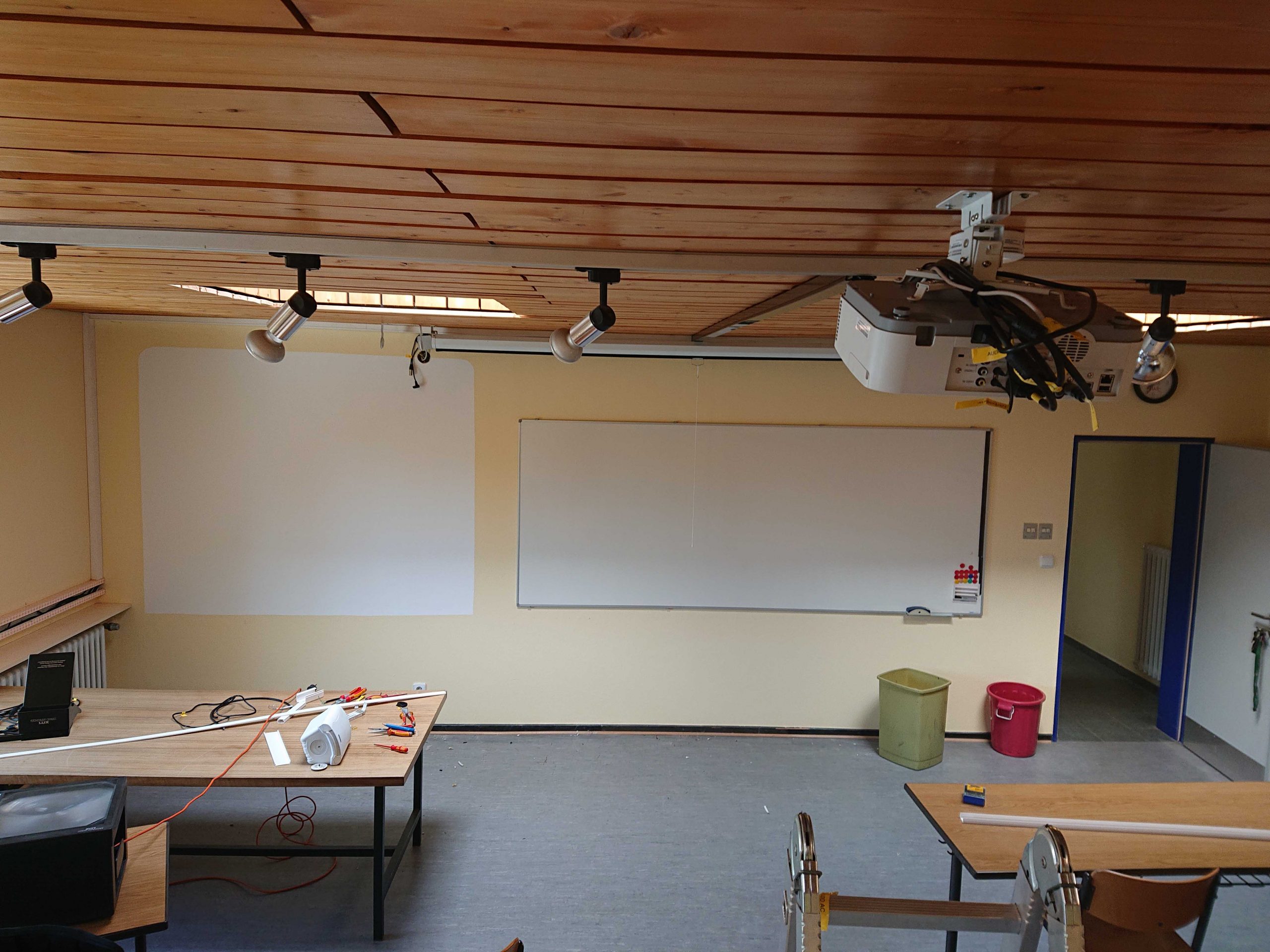
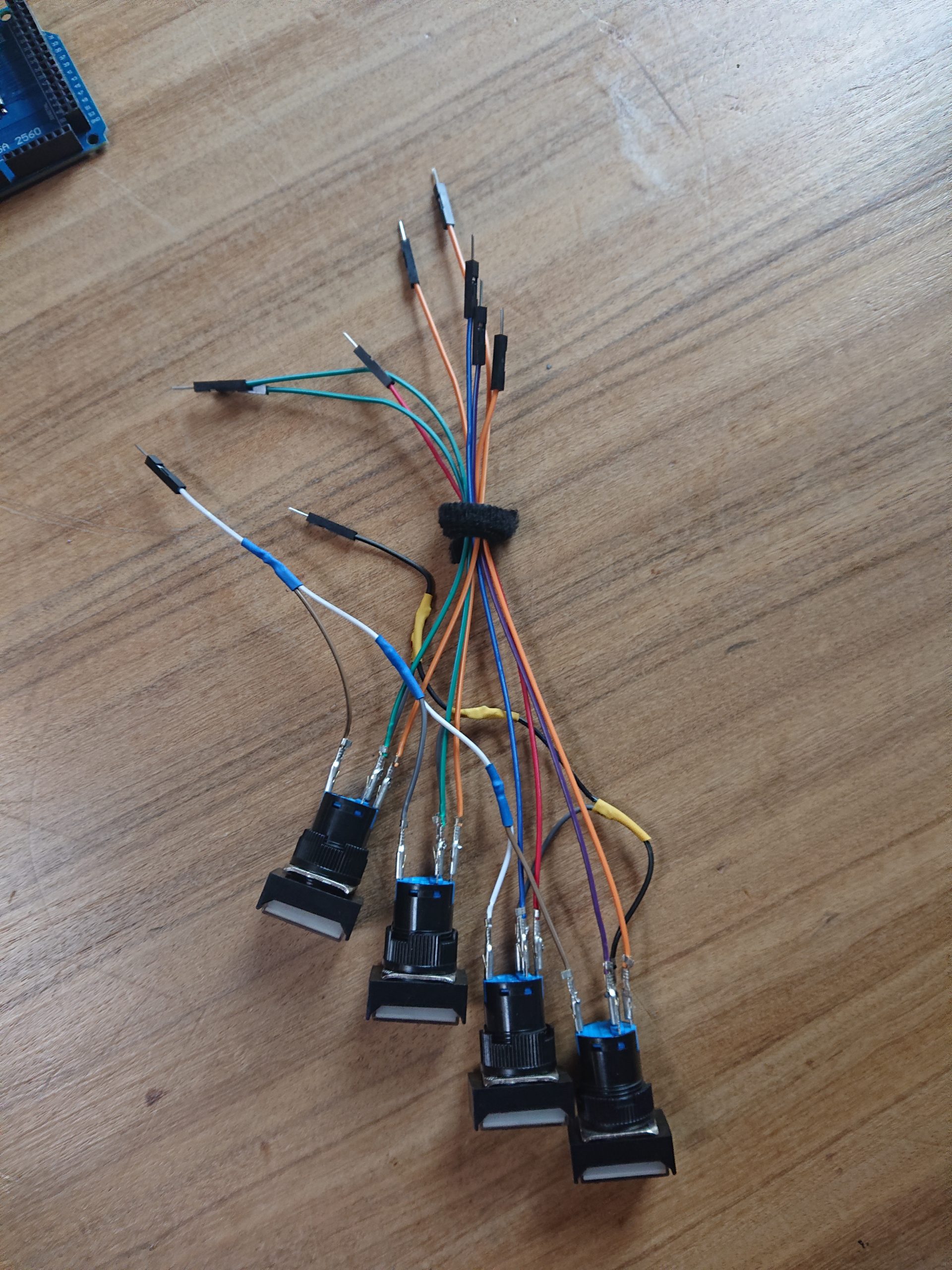
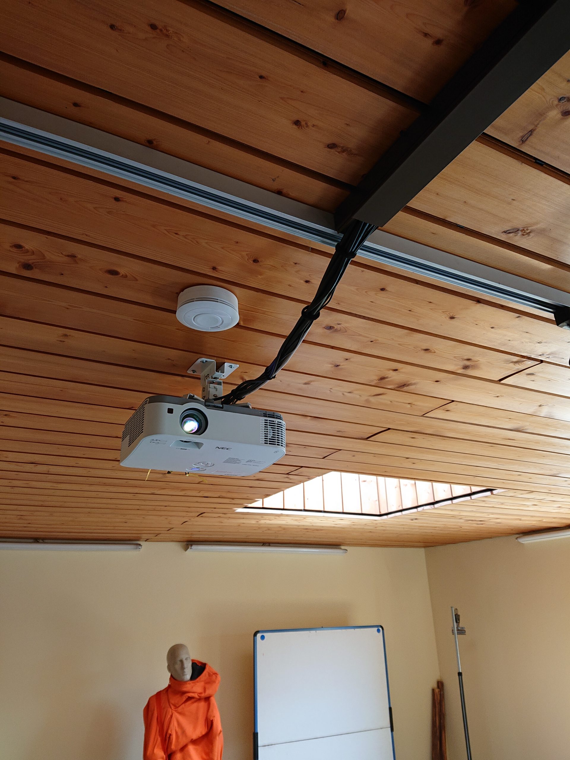
In the following a commercial projector was installed as represented in Figure 3, necessary cables were installed and the closed system was wired correctly. The projector is controlled via the serial interface using an Arduino Mega with ATmega2560 microcontroller. The processor is clearly overpowered, but the number of available connectors on the board facilitates the installations based on it. Self-recovery LED buttons are used to provide the user with direct feedback on which action is currently active.
This setup reflects the necessary basics of the installation. Of course a touch panel and much more can be installed as well

Power installation
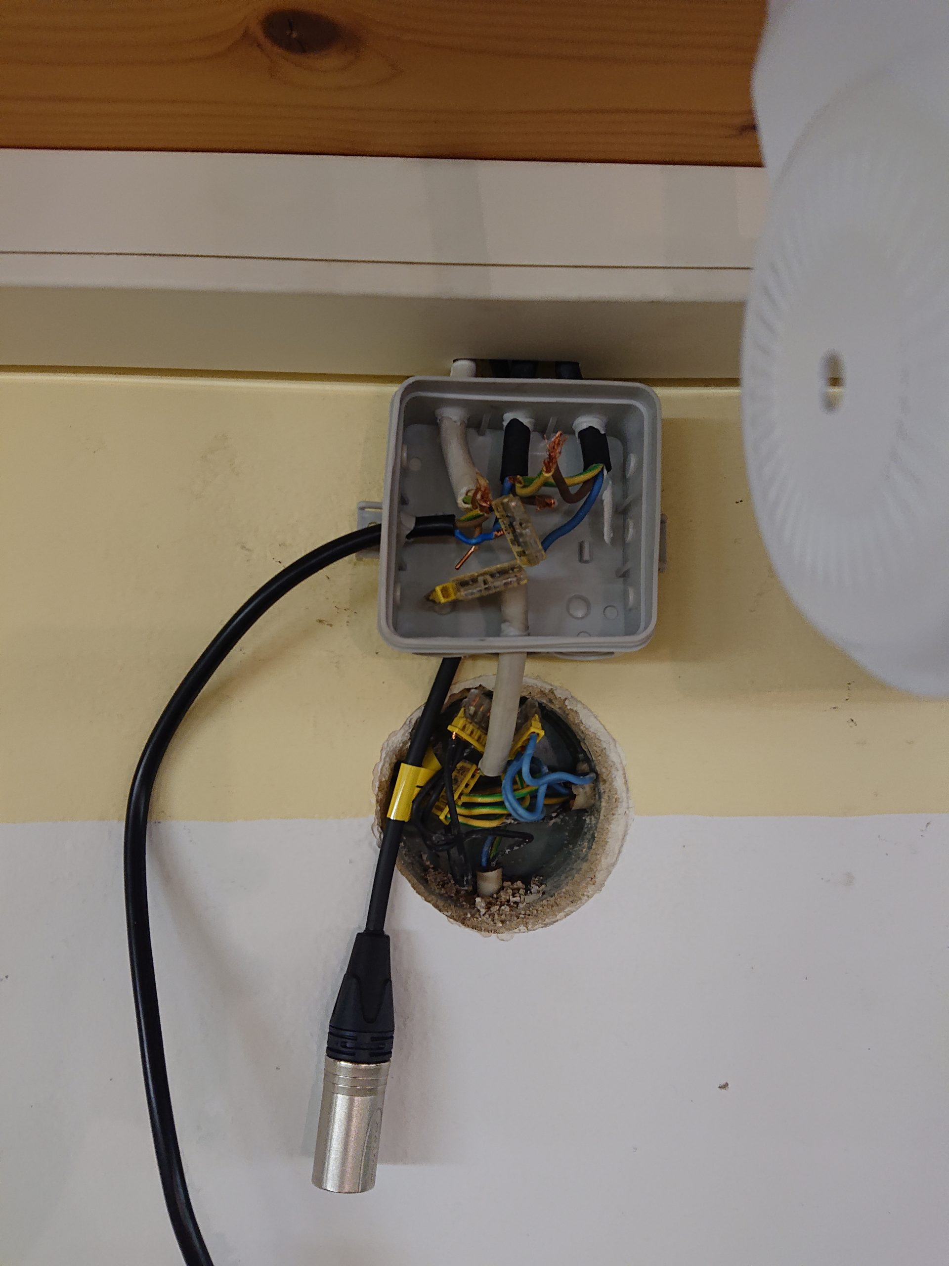
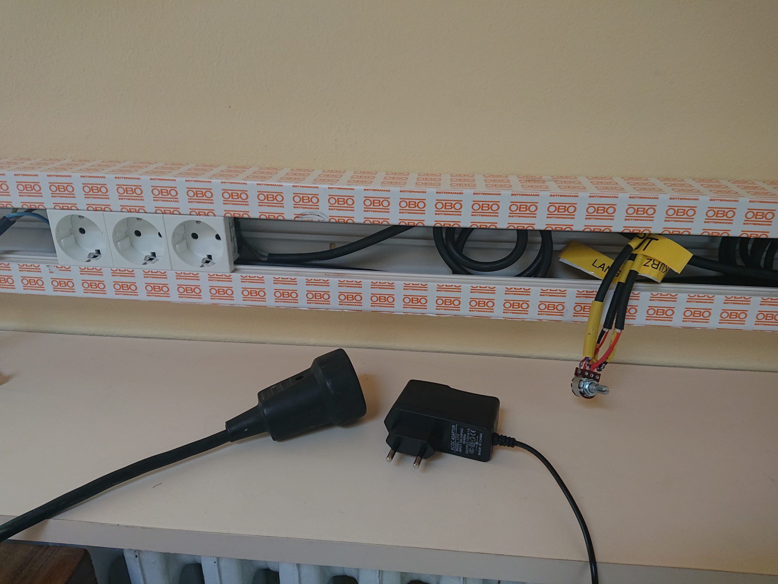
At the height of the left audio box, a power distributor is accessible. This supplies mains voltage for the entire installation. Four consumers are addressed: The projector itself gets a supply line, each of the boxes needs a power connection and finally another power line supplies the control unit (sockets and Arduino).
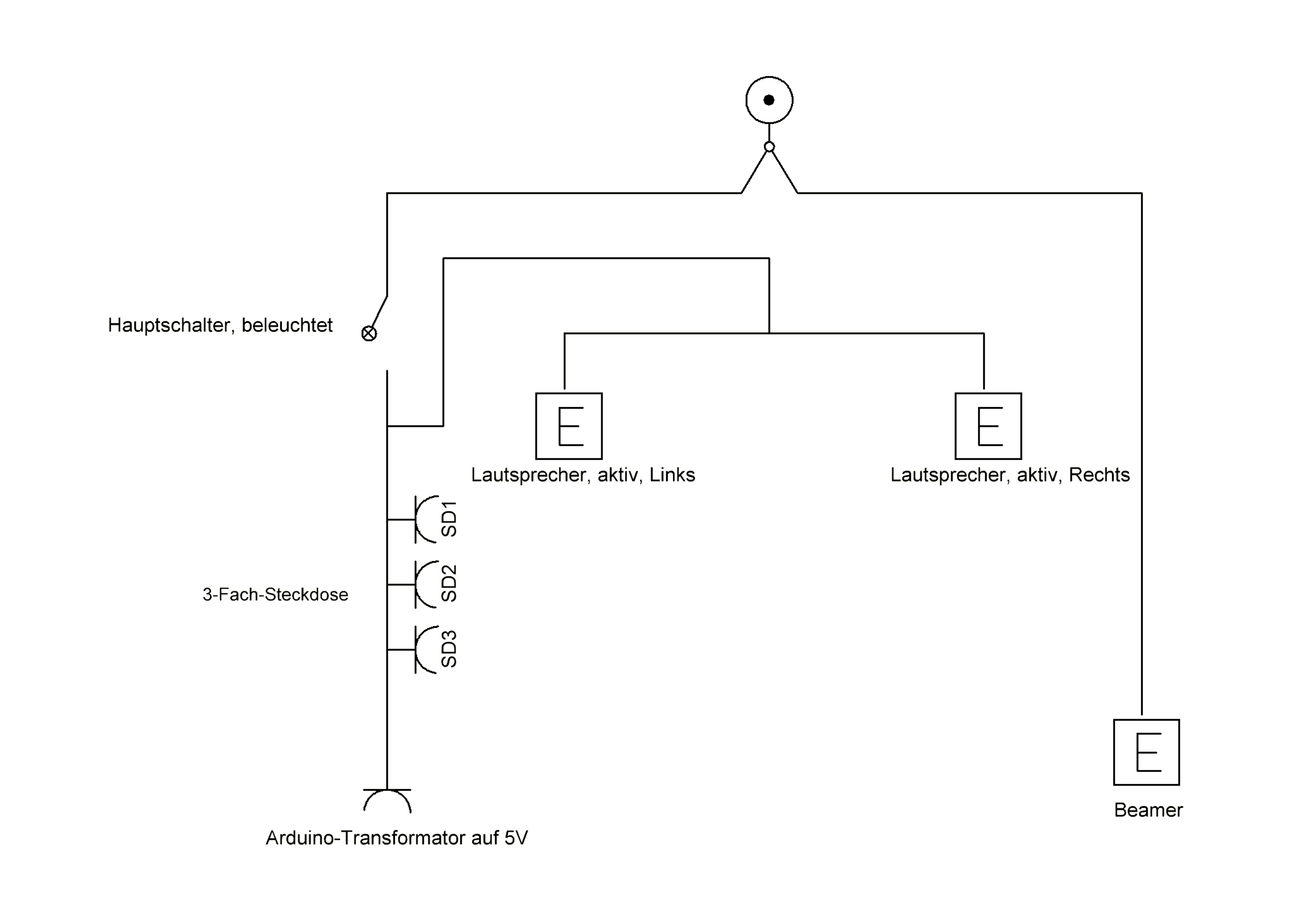
However, the cable routing is to be changed somewhat, which will result in a more complicated installation, but will offer significant added value. Only two power lines go out from the distributor: One to the projector and one to the control unit. A main switch is installed on the latter, which then supplies power to the control unit itself, but also to the two boxes. The projector is thus on continuous current and the three remaining consumers are controlled via the main switch. It doesn’t harm the projector to be on standby all the time, on the contrary: The lamp has the possibility to cool down completely, which increases the lifetime of the projector. A schematic diagram is shown in Figure 4 below.
Video signal
The projector provides a variety of ways to capture an image signal. Of course, it is possible to provide all these connections externally, but in this case it would be inefficient, because the RCA connection, for example, would probably never be used, there would be additional costs and effort for this installation.
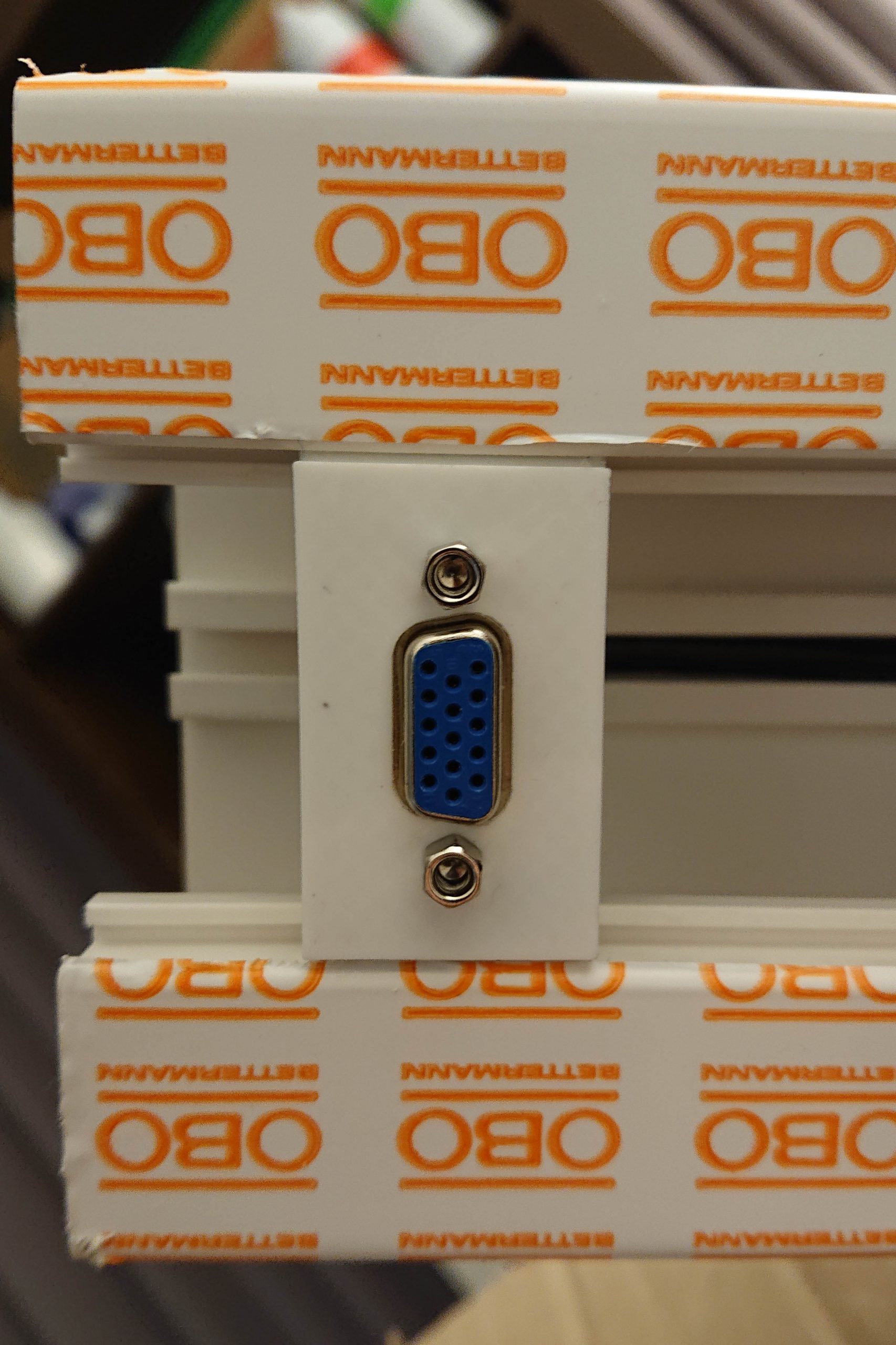
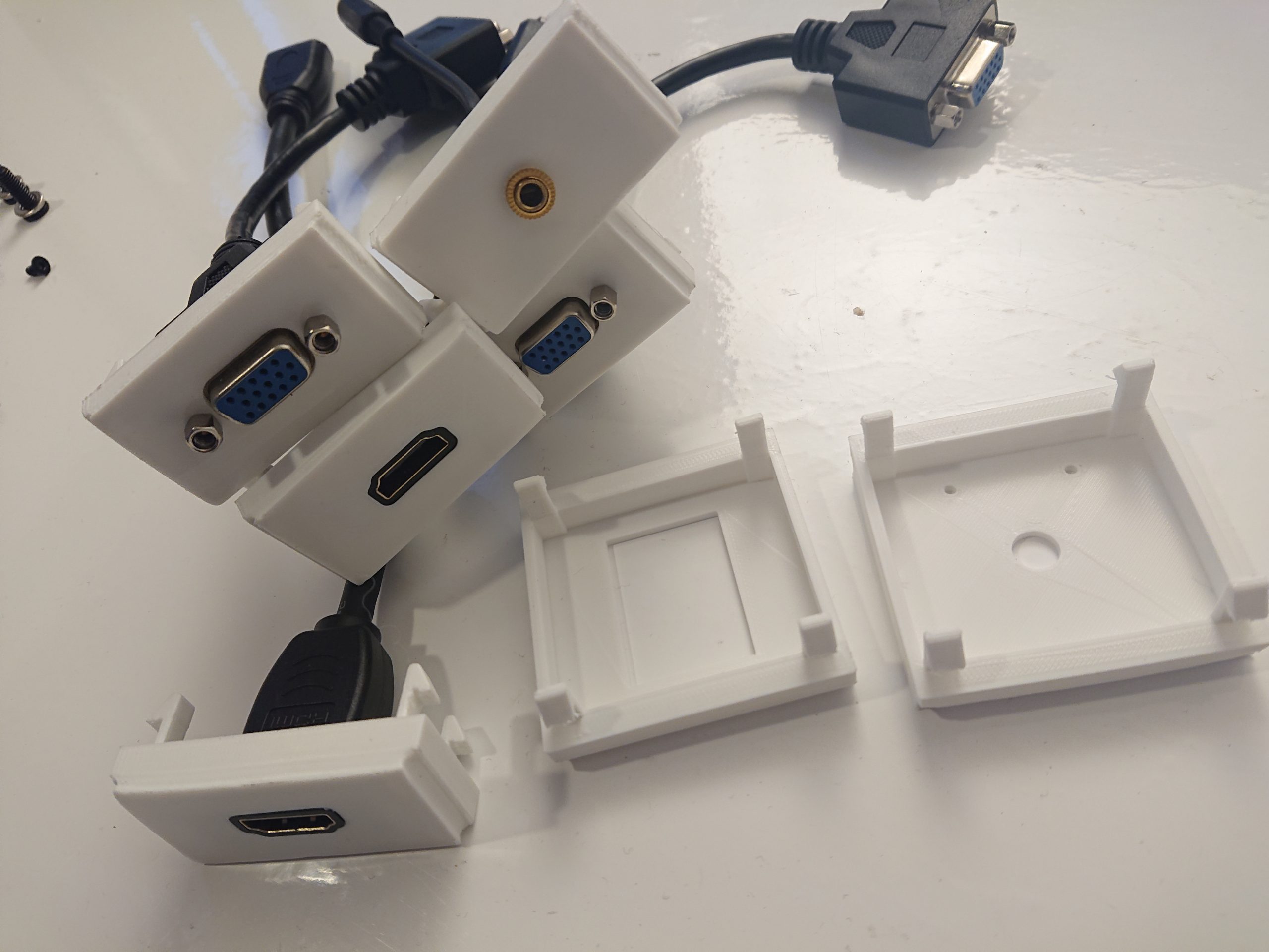
So what is the long term plan for the installation? Of course, presentations must be able to be shown with an external notebook. An HDMI connection is therefore mandatory. Since a presentation computer is planned on site, a second HDMI connection is required to avoid re-connection. For older hardware models an analogue VGA connection completes the setup.
Experience has shown that another problem with presentations is the missing presentation screen, which allows the lecturer to see the output of the projector mirrored without having to constantly turn around. Since the projector supports the output of a monitor signal, this should be used and a VGA output allows the connection of a monitor.
Audio signal
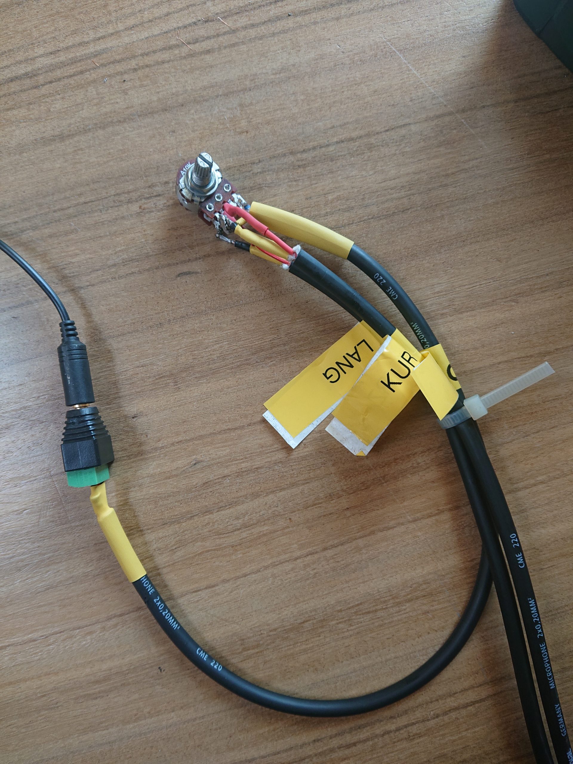
A problem here is the difference between analog (VGA) and digital data transmission (HDMI). With the latter, the sound is delivered directly to the projector, whereas with analogue transmission it has to be supplied additionally. The sound should also have to be adjusted using only one control.
To solve this problem, the following procedure is to be followed: Since the sound provided by HDMI cannot be intercepted, but ends up directly in the projector, the jack plug is also routed directly to the projector and fed into it. The sound output of the video projector is now routed back to the control unit via a jack cable, the volume can be adjusted via a potentiometer and then divided into right and left channels and routed to the corresponding speaker (Figure 5). In this way there is no difference in volume between the connections, no remote control is required and the sound of the HDMI signal does not have to be put out by the user in the computer via jack. A convenient and foolproof solution.

Control Unit
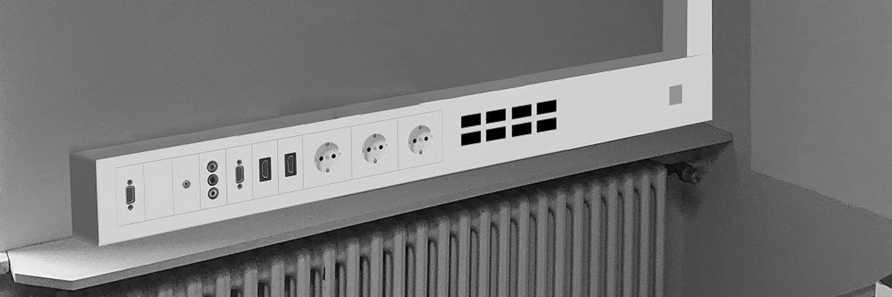
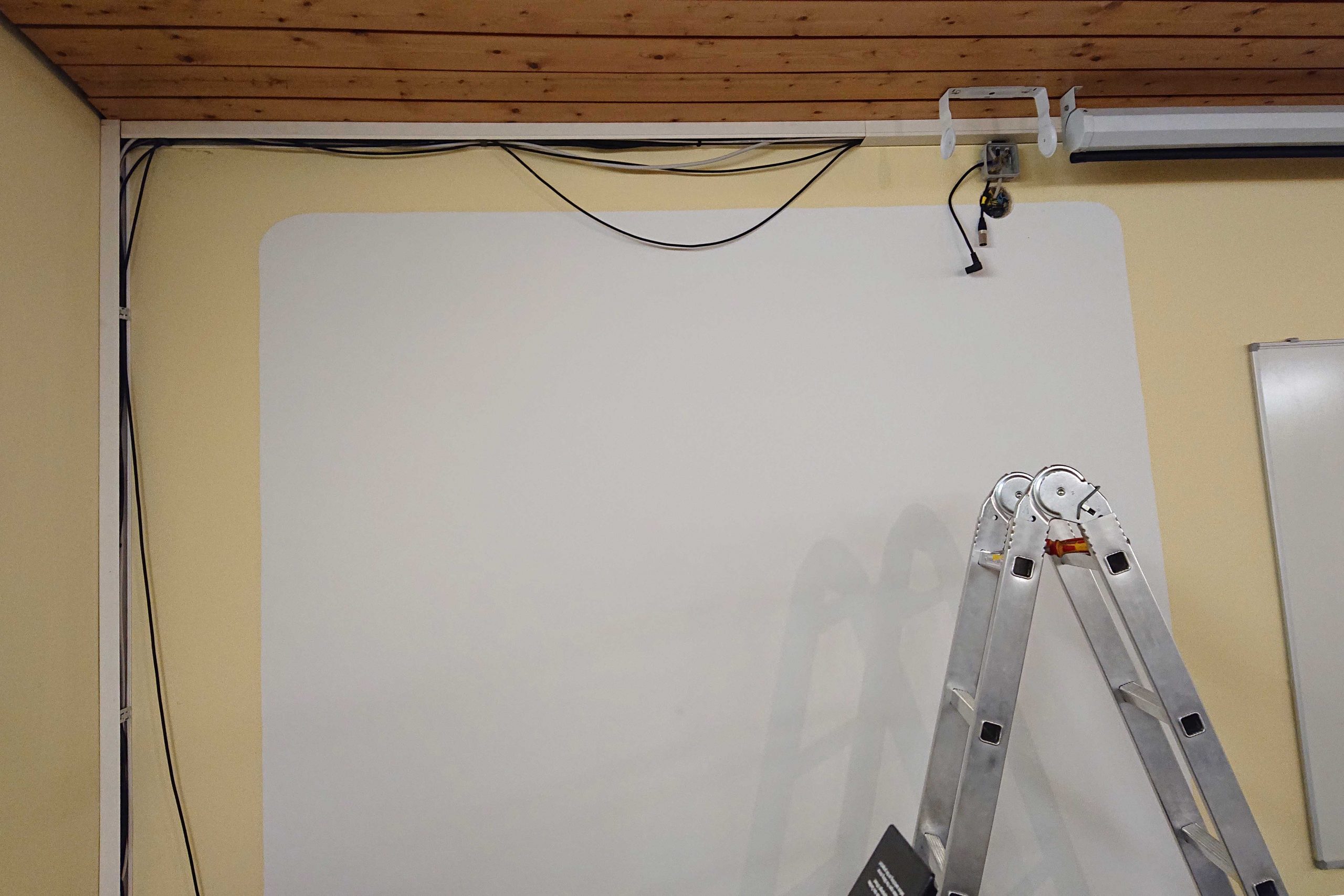
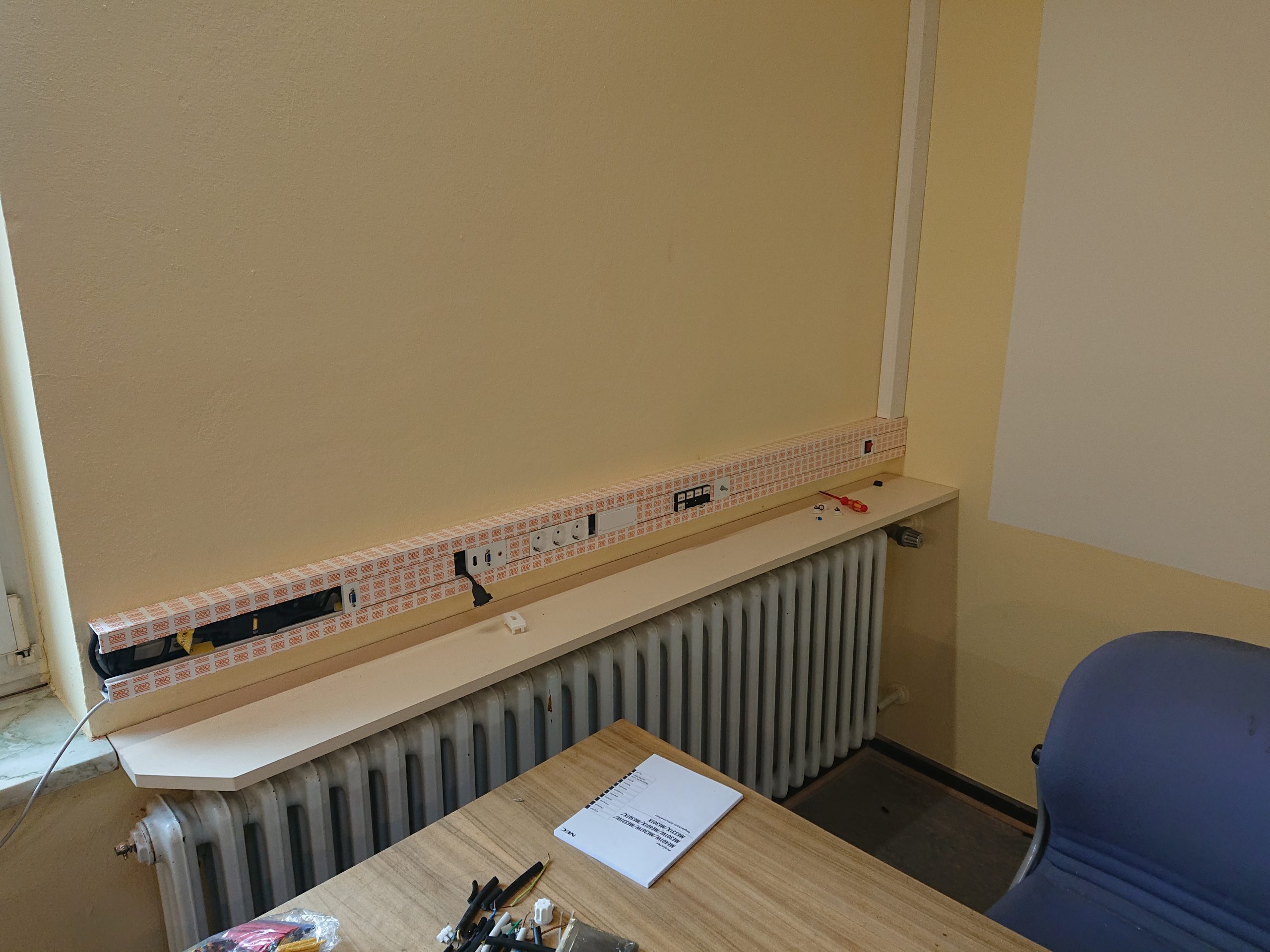
The device installation channel should be equipped directly with the connections for the projector and three AC-sockets. A monitor output connector should also be installed, which mirrors the current projector image. The control unit with buttons should also be directly integrated and there should be a potentiometer to control the volume. A main switch controls the power connection as shown in Figure 4. The cables run space-savingly and discreetly hidden in the cable duct, which nestles in the corner. A photomontage is shown in Figure 6 below.
Materials & Methods
Components
- Arduino Mega 2560 R3 (ATmega2560) Atmel Microcontroller
- Power Supply 12 VDC 2 A
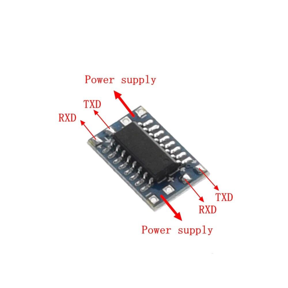
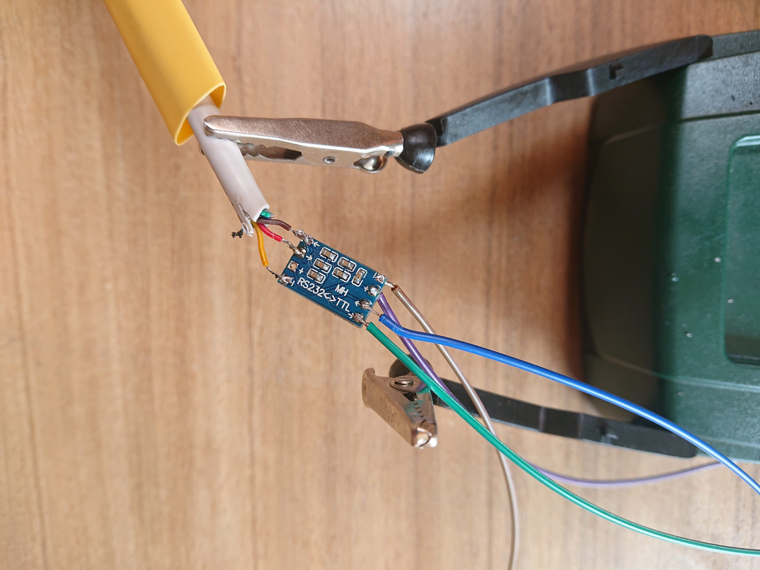
- MAX3232 mini seriell TTL Konverter bidirektional
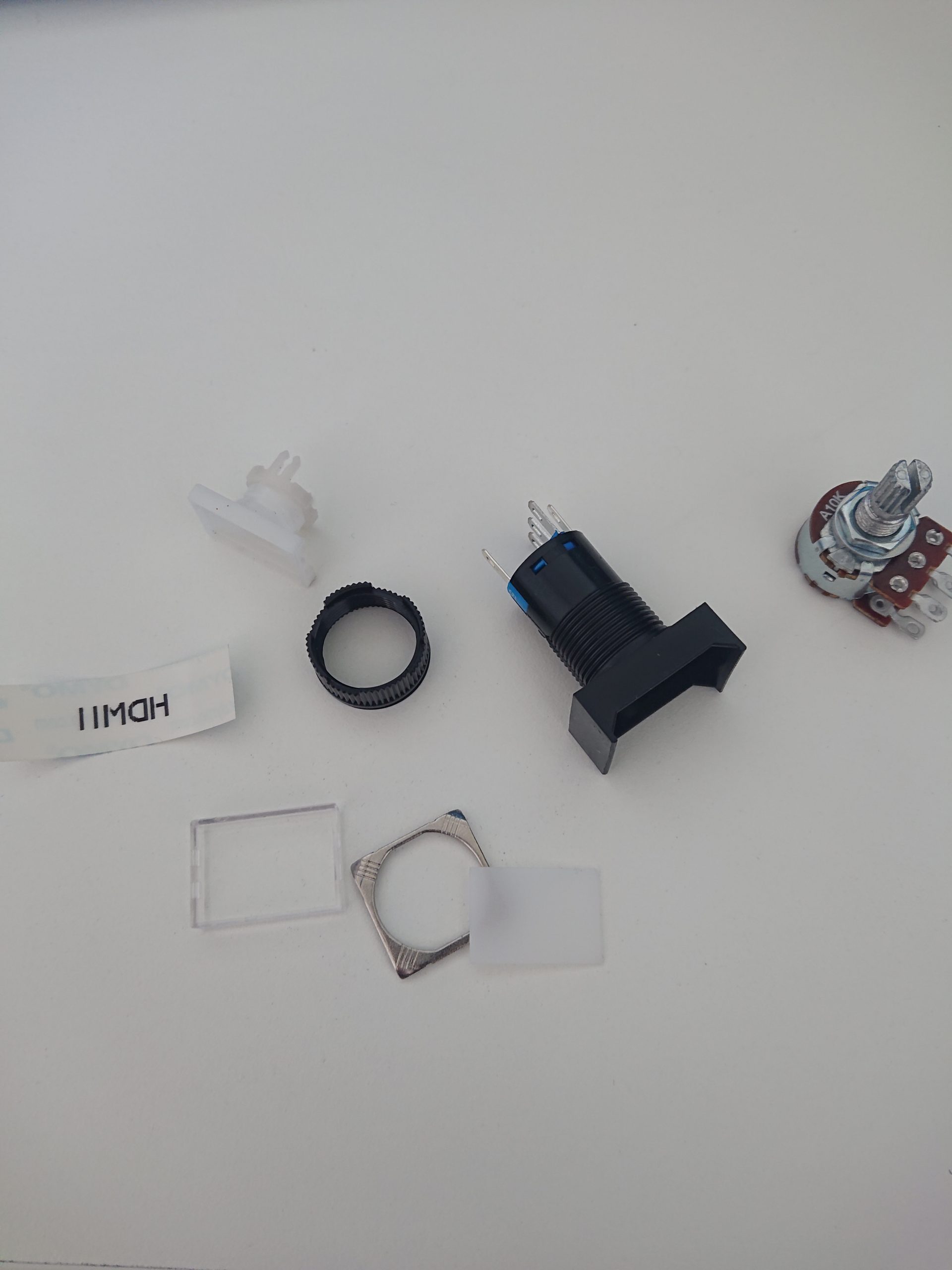
- Self-recovery LED switches 5V 16 mm
- Dupont 2.54 connector cables
- Power Switch 250 V 15 A
For Audio: - 3.5 mm Klinke Stereo Adapter, male | (Cheaper option)
- Rotary Potentionmeter: Stereo, 100 kOhm, logarithmic
- Omnitronic C-50A active stereo speaker
For Debugging: - USB 2.0 to RS232 9 Pin Seriell Adapter
Cable-Channel: - Obo-Bettermann: Geräteeinbaukanal Rapid 45
Software
- Autodesk Inventor Professional 2019 (Build: 265, Release: 2019.2)
- Fritzing beta (Ver. 0.9.4 )
- Arduino IDE 1.8.10 (Board: Arduino Mega, Processor: ATmega2560, Programmer: AVRISP mkII)
- Libraries for Arduino IDE: Software.Serial.h
- HTerm
General Methods
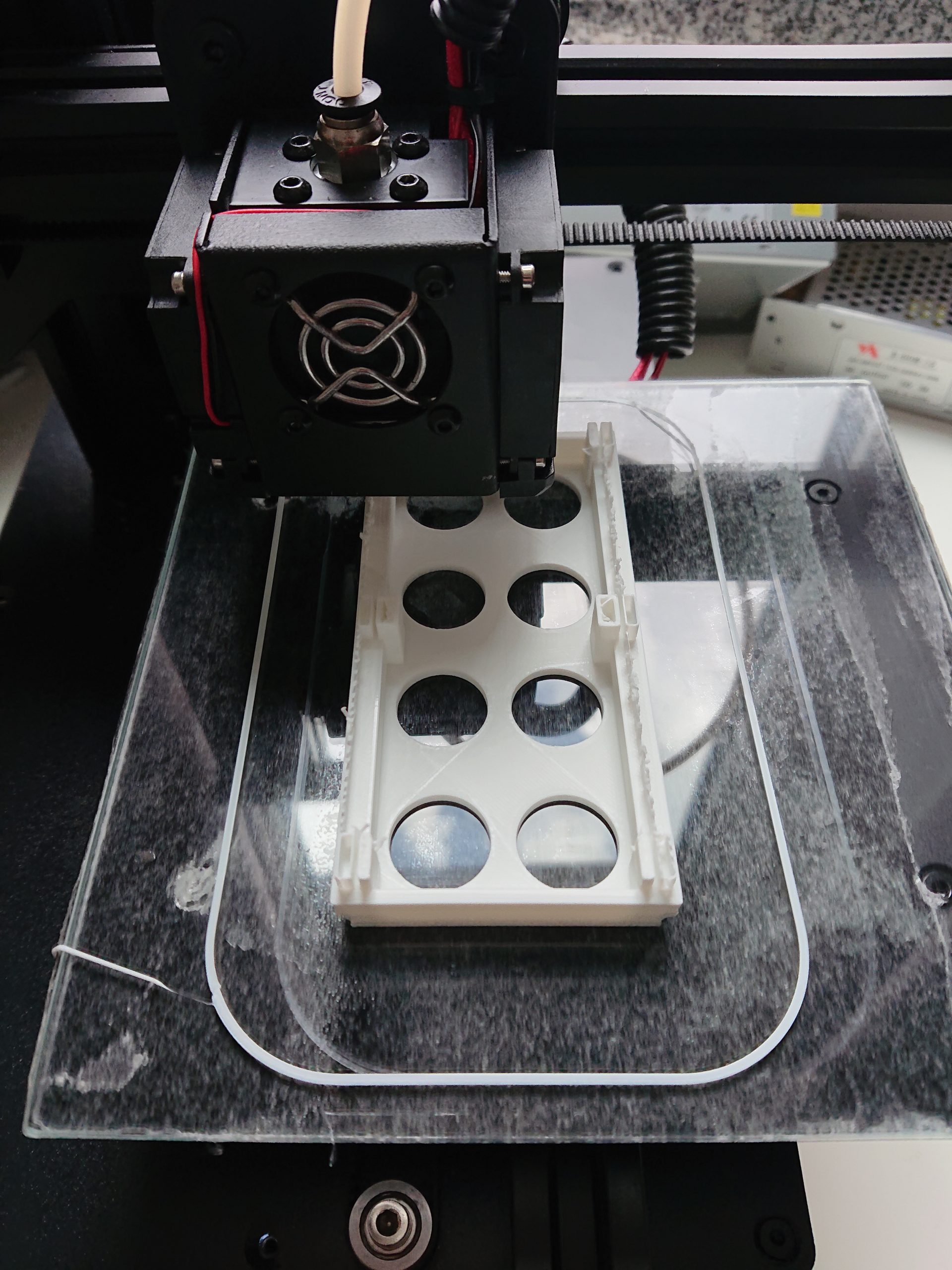
All housing components were printed in PLA filament on a 3D printer. The individual covers for the cable channel also were 3d modeled in Inventor and printed in PLA. The electronic running at 5 VDC used 0.5 mm² of stranded cables. Crimped Dupont 2.64 mm connectors were used as plug or 2.8 mm female crimp connecntions for the switches. For the 250 V circiut single wire 1.5 mm² was used with 6.3 mm insulated crimp connectors.
The program code was uploaded to the microprocessor via USB interface. The serial monitor feature of HTerm was used to visualize and calibrate the serial signals between the microcontroller and the projector in hexadecimal format (HEX).
The serial commands may very from every projector ir printer manufacturer. Be sure to have the serial commands for the specific projector you are using. In this project the projector was NEC ME316W.
Source code
At the beginning the brightness for the LED buttons is defined. With the control switched on without selection, the brightness should be 128, i.e. half the tonal range.
In the active state a button should change to full brightness, i.e. 255 steps.
Then the projector specific serial commands with their corresponding function are defined.
Afterwards the pins of the buttons and corresponding LEDs must be defined.
//define led brightness
#define LIGHT_LOW 128
#define LIGHT_HIGH 255

//serial commands
const byte c_beamer_on[] = {0x02, 0x00, 0x00, 0x00, 0x00, 0x02};
const byte c_beamer_off[] = {0x02, 0x01, 0x00, 0x00, 0x00, 0x01};
const byte c_hdmi_1[] = {0x02, 0x03, 0x00, 0x00, 0x02, 0x01, 0x1A, 0x22};
const byte c_hdmi_2[] = {0x02, 0x03, 0x00, 0x00, 0x02, 0x01, 0x1B, 0x23};
const byte c_vga[] = {0x02, 0x03, 0x00, 0x00, 0x02, 0x01, 0x01, 0x09};
const byte c_mute_video[] = {0x02, 0x10, 0x00, 0x00, 0x00, 0x12};
const byte c_unmute_video[] = {0x02, 0x11, 0x00, 0x00, 0x00, 0x13};
const byte c_mute_sound[] = {0x02, 0x12, 0x00, 0x00, 0x00, 0x14};
const byte c_unmute_sound[] = {0x02, 0x13, 0x00, 0x00, 0x00, 0x15};
//const byte ratio[] = {0x, 0x, 0x, 0x, 0x, 0x};

// define button pins
const int button_beamer_on = 31;
const int button_beamer_off = 33;
const int button_hdmi_1 = 35;
const int button_hdmi_2 = 37;
const int button_vga = 39;
const int button_mute_sound = 41;
const int button_mute_video = 42;
const int button_ratio = 45;

// define led pins
const int led_beamer_on = 5;
const int led_beamer_off = 6;
const int led_hdmi_1 = 7;
const int led_hdmi_2 = 8;
const int led_vga = 9;
const int led_mute_sound = 10;
const int led_mute_video = 11;
const int led_ratio = 12;

typedef struct inVector {
//buttons (only true on rising edge)
  bool beamer_on;
  bool beamer_off;
  bool hdmi_1;
  bool hdmi_2;
  bool vga;
  bool mute_sound;
  bool mute_video;
  bool ratio;
}inVector;

typedef struct outVector {
  //LEDs
  bool beamer_on;
  bool beamer_off;
  bool hdmi_1;
  bool hdmi_2;
  bool vga;
  bool mute_sound;
  bool mute_video;
  bool ratio;
}outVector;

typedef enum beamerInput {none, hdmi_1, hdmi_2, vga} beamerInput;

void send_command(const byte * command, int len) {
  Serial1.write(command, len);
}

void fillInVector(inVector * inV) {
  static bool last_beamer_on = true;
  static bool last_beamer_off = true;
  static bool last_hdmi_1 = true;
  static bool last_hdmi_2 = true;
  static bool last_vga = true;
  static bool last_mute_sound = true;
  static bool last_mute_video = true;
  static bool last_ratio = true;

  //reset all Values
  memset(inV, 0, sizeof(inVector));


  if (!digitalRead(button_beamer_on) && last_beamer_on) {
    inV->beamer_on = true;
    last_beamer_on = false;
    return;
  }
  last_beamer_on = digitalRead(button_beamer_on);

  if (!digitalRead(button_beamer_off) && last_beamer_off) {
    inV->beamer_off = true;
    last_beamer_off = false;
    return;
  }
  last_beamer_off = digitalRead(button_beamer_off);

  if (!digitalRead(button_hdmi_1) && last_hdmi_1) {
    inV->hdmi_1 = true;
    last_hdmi_1 = false;
    return;
  }
  last_hdmi_1 = digitalRead(button_hdmi_1);

  if (!digitalRead(button_hdmi_2) && last_hdmi_2) {
    inV->hdmi_2 = true;
    last_hdmi_2 = false;
    return;
  }
  last_hdmi_2 = digitalRead(button_hdmi_2);

  if (!digitalRead(button_vga) && last_vga) {
    inV->vga = true;
    last_vga = false;
    return;
  }
  last_vga = digitalRead(button_vga);

  if (!digitalRead(button_mute_sound) && last_mute_sound) {
    inV->mute_sound = true;
    last_mute_sound = false;
    return;
  }
  last_mute_sound = digitalRead(button_mute_sound);

  if (!digitalRead(button_mute_video) && last_mute_video) {
    inV->mute_video = true;
    last_mute_video = false;
    return;
  }
  last_mute_video = digitalRead(button_mute_video);

  if (!digitalRead(button_ratio) && last_ratio) {
    inV->ratio = true;
    last_ratio = false;
    return;
  }
  last_ratio = digitalRead(button_ratio);
}

void writeOutVector(outVector * outV) {
  analogWrite(led_beamer_on, outV->beamer_on?LIGHT_HIGH:LIGHT_LOW);
  analogWrite(led_beamer_off, outV->beamer_off?LIGHT_HIGH:LIGHT_LOW);
  analogWrite(led_hdmi_1, outV->hdmi_1?LIGHT_HIGH:LIGHT_LOW);
  analogWrite(led_hdmi_2, outV->hdmi_2?LIGHT_HIGH:LIGHT_LOW);
  analogWrite(led_vga, outV->vga?LIGHT_HIGH:LIGHT_LOW);
  analogWrite(led_mute_sound, outV->mute_sound?LIGHT_HIGH:LIGHT_LOW);
  analogWrite(led_mute_video, outV->mute_video?LIGHT_HIGH:LIGHT_LOW);
  analogWrite(led_ratio, outV->ratio?LIGHT_HIGH:LIGHT_LOW);
}

void stateMachine(inVector * inVec, outVector * outVec) {
  static beamerInput input = none;
  static bool mute_sound = false;
  static bool mute_video = false;
  static bool status_beamer = false;

  if (inVec->beamer_on) {
    send_command(c_beamer_on, 6);
    status_beamer = true;
  }
  if (inVec->beamer_off) {
    send_command(c_beamer_off);
    status_beamer = false;
  }
  if (inVec->hdmi_1) {
    send_command(c_hdmi_1);
    input = hdmi_1;
  }
  if (inVec->hdmi_2) {
    send_command(c_hdmi_2);
    input = hdmi_2;
  }
  if (inVec->vga) {
    send_command(c_vga);
    input = vga;
  }
  if (inVec->mute_sound) {
    if (mute_sound) {
      send_command(c_unmute_sound);
      mute_sound = false;
    } else {
      send_command(c_mute_sound);
      mute_sound = true;
    }
  }
  if (inVec->mute_video) {
    if (mute_video) {
      send_command(c_unmute_video);
      mute_video = false;
    } else {
      send_command(c_mute_video);
      mute_video = true;
    }
  }


  //reset out vector
  outVec->hdmi_1 = false;
  outVec->hdmi_2 = false;
  outVec->vga = false;
  outVec->ratio = false;

  switch (input) {  //set signal led
    case hdmi_1:
      outVec->hdmi_1 = true;
    break;

    case hdmi_2:
      outVec->hdmi_2 = true;
    break;

    case vga:
      outVec->vga = true;
    break;

    case none:
    default:
    break;
  }

  outVec->mute_sound = mute_sound;
  outVec->mute_video = mute_video;
  outVec->beamer_on = status_beamer;
  outVec->beamer_off = !status_beamer;
}

void setup() {
  //set pin modes
  //inputs
  pinMode(button_beamer_on, INPUT_PULLUP);
  pinMode(button_beamer_off, INPUT_PULLUP);
  pinMode(button_hdmi_1, INPUT_PULLUP);
  pinMode(button_hdmi_2, INPUT_PULLUP);
  pinMode(button_vga, INPUT_PULLUP);
  pinMode(button_mute_sound, INPUT_PULLUP);
  pinMode(button_mute_video, INPUT_PULLUP);
  pinMode(button_ratio, INPUT_PULLUP);
  //outputs
  pinMode(led_beamer_on, OUTPUT);
  pinMode(led_beamer_off, OUTPUT);
  pinMode(led_hdmi_1, OUTPUT);
  pinMode(led_hdmi_2, OUTPUT);
  pinMode(led_vga, OUTPUT);
  pinMode(led_mute_sound, OUTPUT);
  pinMode(led_mute_video, OUTPUT);
  pinMode(led_ratio, OUTPUT);

  //start serial communication
  Serial1.begin(9600);
}

void loop() {
  static inVector inVec;
  static outVector outVec;

  fillInVector(&inVec);
  stateMachine(&inVec, &outVec);
  writeOutVector(&outVec);
}
Installation info & schemes


Results
Impressions


PLEASE PROVIDE CIRCUIT DIAGRAM OF SYSTEM.