
Abstract
In this project, the idea of the adaptive brake light was reinterpreted using an Arduino Nano (ATMEGA328P) microcontroller. With a transistor as switching unit and an acceleration or GPS sensor, the components are connected in between the braking signal – only one additional power cable needs to be pulled. Any vehicle type can be easily retrofitted in this way without complicated wiring or the need to detect pedal force. The code was programmed using existing Arduino libraries, the cases were 3D printed and the finished modules were tested in practice. The total price of required components does not exceed $15.
Attention: This project is written for international audience. It is imperative to observe the legal regulations of your own country to determine whether such an installation is compatible with the applicable regulations. It is also necessary to have advanced knowledge in the field of electrical engineering in order to guarantee a professional and safe installation. In the worst case, the brake light may fail completely or the cables may catch fire, in both cases causing immense damage and danger to yourself and others. The authors hereby dissociate themselves completely from any responsibility! Act on your own responsibility!Introduction
According to the ADAC, rear-end collisions are the second most frequent cause of accidents after disregarding the right of way and are often associated with too little distance between the person behind. Inattentiveness or misjudgement of the drivers ultimately makes an accident inevitable. Collisions often result in serious injuries to those involved in both the front and rear vehicle.
If, in an emergency, a driver does everything correctly and performs an emergency stop, there is still a great danger of being involved in a serious accident by the vehicle behind.
Mercedes-Benz (and by now some other vehicle manufacturers like BMW and Audi) countered this problem with an intelligent solution: The adaptive brake light. In the research project by Mercedes-Benz, the number of rear-end collisions was titled 17% of the total number of accidents in Germany and 31% in the USA according to the National Highway Traffic Safety Administration (NHTSA).
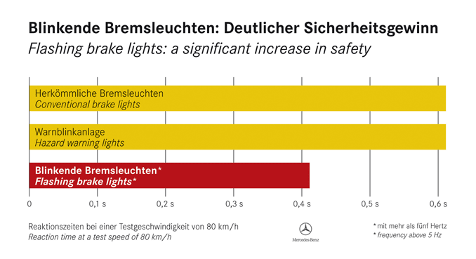
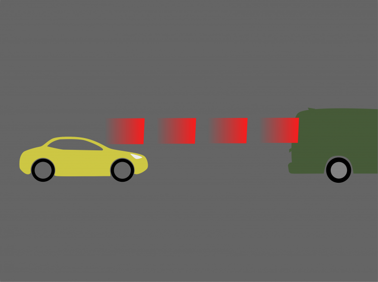
After the reasearchers had tested various setups, the best results regarding the reaction of the rear driver were achieved by flashing the brake light during emergency braking. The braking distance could be reduced by 4.4 m at a speed of 80 km/h, and 5.5 m at 100 km/h by this method according to their unpublished study.
In the following video the technology is demonstrated on a Mercedes-Benz model:

Reason enough to think about a method how this system can be adapted in an easy way. In the following an attempt was made to build a system with the simplest possible means in order to provide every driver a higher level of road safety. The system described here can easily be retrofitted in any non-specific vehicle. Due to the additional size and price, a variant consisting of a microcontroller and accelerometer was first developed, which can be supplemented by a GPS module if not only acceleration but also speed should be included in the algorithm
The aim of the project was also to work cost-efficiently. A variant based only on an acceleration sensor with a total of approx. $10 material costs, and a variant with the addition of a GPS module with approx. $15 material costs per unit are presented.
Materials & Methods
Components
- Microcontroller: ATMEGA328P (Arduino Nano Clone) ($2.5)
- Accelleration-sensor: GY-521 MPU-6050 ($1.5)
- GPS-sensor: GY-NEO6MV2 ($6.15)
- Transistor: BD139 Genuine ON Semiconductor NPN 1.5 A / 80 V To-126 ZBDE W0HW ($0.20) (Polarity here is C/E/B! Regular C/B/E polarity will of course work aswell)
- LEDs: T10 COB-LED (Socket depends on vehicle) (4x á $0.97 = $3.88)
Software
- Autodesk Inventor Professional 2019 (Build: 265, Release: 2019.2)
- Fritzing beta (Ver. 0.9.4 )
- Arduino IDE 1.8.10 (Board: Arduino Nano, Processor: ATmega328P, Programmer: AVRISP mkII)
- Libraries for Arduino IDE:
– without GPS: Wire.h
– with GPS: Wire.h, Software.Serial.h, TinyGPS.h
Methods
All housing components were printed in PLA filament on a 3D printer. The electronic components were soldered using 0.5 m² of stranded cables. Crimped Dupont 2.64 mm connectors (Also known as “arduino cables”) were used as plug connections.
The program code was uploaded to the microprocessor via USB interface. The serial plotter implemented in the Arduino IDE was used to visualize and calibrate the signals detected by the acceleration sensor.
Source code
The operating principle of the source code is based on an interruption of the light signal using the transistor. This means that without triggering the sketch (i.e. at slow speeds or only slight changes in acceleration) the current sent by the brake pedal is passed through the microcontroller to light up the brake lights. Only as soon as the acceleration sensor detects an acceleration above a defined threshold value and (if used) the GPS sensor detects a speed above a defined threshold value, the sketch is triggered and interrupts the continuous light signal for a defined time by the parameters BLINKON and BLINKOFF, resulting in a flashing effect. If the sketch is once activated, the flashing will then last for a defined STOPPINGTIME, independent of the currently read out data – so that, as in the example video, the flashing signal will last until the vehicle has come to a standstill or for a short time during the strong speed reduction in order to obtain the desired warning effect.
#include "Wire.h"
#include "SoftwareSerial.h"
#include "TinyGPS.h"


#define STOPPINGTIME 1500   // in ms
#define G_THRESHOLD 1.1   // activate above threshold
#define G 2.7e8             // = 1 g
#define BLINKON 75          // in ms
#define BLINKOFF 75         // in ms
#define INITFILT 400        // number of values averaged to get initial acceleration
#define FILT 140            // number of values averaged to get current acceleration

#define V_THRESHOLD 100   // in km/h
#define MAXFAILEDGPSBYTES 1000  // number of bytes received from gps to abort without valid gps sequence
#define MAXTIMESINCELASTFIX 2000  // in ms


const int ledPin = 11;
const int ledPin2 = 13;
const int MPU_addr = 0x68;  //I2C address
const int GPSrxPin = 3;
const int GPStxPin = 4;


bool blinkStatus, ledStatus, risingEdge;

unsigned long endTime, toggleTime;

double gforce, oldforce;

int16_t Xi, Yi, Zi;
int32_t Xc = 0, Yc = 0, Zc = 0;
double X, Y, Z, AccP;

int16_t Xbuf[FILT] = {0}, Ybuf[FILT] = {0}, Zbuf[FILT] = {0};
int bufpos = 0, i;
int32_t tmp;


SoftwareSerial gpsSerial(GPSrxPin, GPStxPin);  //rx (D3),tx (D4) for GPS
TinyGPS gps; // create gps object
float speed = 0;  //vehicle speed in km/h
long lat, lon;
unsigned long fix_age;
bool goodfix;


void setup() {
  //Connect to G-Sensor
  Wire.begin();
  Wire.beginTransmission(MPU_addr);
  Wire.write(0x6B);  // PWR_MGMT_1 register
  Wire.write(0);     // set to zero (wakes up the MPU-6050)
  Wire.endTransmission(true);

  Serial.begin(9600);     // for USB monitor

  gpsSerial.begin(9600); // connect gps sensor

  for (i = 0; i<INITFILT; i++) {

    Wire.beginTransmission(MPU_addr);
    Wire.write(0x3B);  // starting with register 0x3B (ACCEL_XOUT_H)
    Wire.endTransmission(false);
    Wire.requestFrom(MPU_addr,6,true); // request a total of 6 registers
    Xc+=Wire.read()<<8|Wire.read();    // 0x3B (ACCEL_XOUT_H) & 0x3C (ACCEL_XOUT_L)
    Yc+=Wire.read()<<8|Wire.read();    // 0x3D (ACCEL_YOUT_H) & 0x3E (ACCEL_YOUT_L)
    Zc+=Wire.read()<<8|Wire.read();    // 0x3F (ACCEL_ZOUT_H) & 0x40 (ACCEL_ZOUT_L)

  }

  Xc = Xc/FILT;
  Yc = Yc/FILT;
  Zc = Zc/FILT;


  pinMode(ledPin, OUTPUT);
  digitalWrite(ledPin, true);
  pinMode(ledPin2, OUTPUT);
  digitalWrite(ledPin2, true);
  blinkStatus = false;
  ledStatus = true;

}

void loop() {

  // GPS read
  i = 0;
  while(gpsSerial.available()) { //Data available?
    if(gps.encode(gpsSerial.read())) {  //GPS telegram complete?
      speed = gps.f_speed_kmph();

      break;  // end while loop
    }

    if (i++ > MAXFAILEDGPSBYTES)  // cancel after MAXFAILEDGPSBYTES bytes without valid telegram
      break;
  }
  //check for valid signal
  gps.get_position(&lat, &lon, &fix_age);
  goodfix = ((fix_age == TinyGPS::GPS_INVALID_AGE) || (fix_age > MAXTIMESINCELASTFIX)) ? false : true;


  //G-Sensor read
  Wire.beginTransmission(MPU_addr);
  Wire.write(0x3B);  // starting with register 0x3B (ACCEL_XOUT_H)
  Wire.endTransmission(false);
  Wire.requestFrom(MPU_addr,6,true); // request a total of 6 registers
  Xbuf[bufpos]=Wire.read()<<8|Wire.read();    // 0x3B (ACCEL_XOUT_H) & 0x3C (ACCEL_XOUT_L)
  Ybuf[bufpos]=Wire.read()<<8|Wire.read();    // 0x3D (ACCEL_YOUT_H) & 0x3E (ACCEL_YOUT_L)
  Zbuf[bufpos]=Wire.read()<<8|Wire.read();    // 0x3F (ACCEL_ZOUT_H) & 0x40 (ACCEL_ZOUT_L)

  tmp = 0;
  for (i = 0; i<FILT; i++) {
    tmp += Xbuf[i];
  }
  Xi = tmp;
  tmp = 0;
    for (i = 0; i<FILT; i++) {
    tmp += Ybuf[i];
  }
  Yi = tmp;
  tmp = 0;
    for (i = 0; i<FILT; i++) {
    tmp += Zbuf[i];
  }
  Zi = tmp;

  X = Yc*Zi - Zc*Yi;
  Y = Zc*Xi - Xc*Zi;
  Z = Xc*Yi - Yc*Xi;

  gforce = sqrt(X*X + Y*Y + Z*Z);

  Serial.print(G_THRESHOLD * G);
  Serial.print(',');
  Serial.print(8e8);
  Serial.print(',');
  Serial.print(G);
  Serial.print(',');
  Serial.println(gforce);
  delay(0);


  // blinkstuff
  risingEdge = false;

  if (blinkStatus) {
    if (gforce > G_THRESHOLD * G) {
      endTime = millis() + STOPPINGTIME;
    }
  } else {
    if ( (gforce > G_THRESHOLD * G) && ( !goodfix || (speed > V_THRESHOLD)) ) {
      risingEdge = true;
      blinkStatus = true;

      endTime = millis() + STOPPINGTIME;
    }
  }

  if (risingEdge) {
    toggleTime = millis() + BLINKOFF;
    digitalWrite(ledPin, false);
    ledStatus = false;
  }

  if (blinkStatus) {
    if (millis() > toggleTime) {
      if (ledStatus) {
        ledStatus = false;
        toggleTime = millis() + BLINKOFF;
        digitalWrite(ledPin, false);
        digitalWrite(ledPin2, false);
      } else {
        ledStatus = true;
        toggleTime = millis() + BLINKON;
        digitalWrite(ledPin, true);
        digitalWrite(ledPin2, true);
      }
    }

    if (millis() > endTime) {
      blinkStatus = false;
      digitalWrite(ledPin, true);
      digitalWrite(ledPin2, true);
    }
  }
}
Results
Setup & Calibration
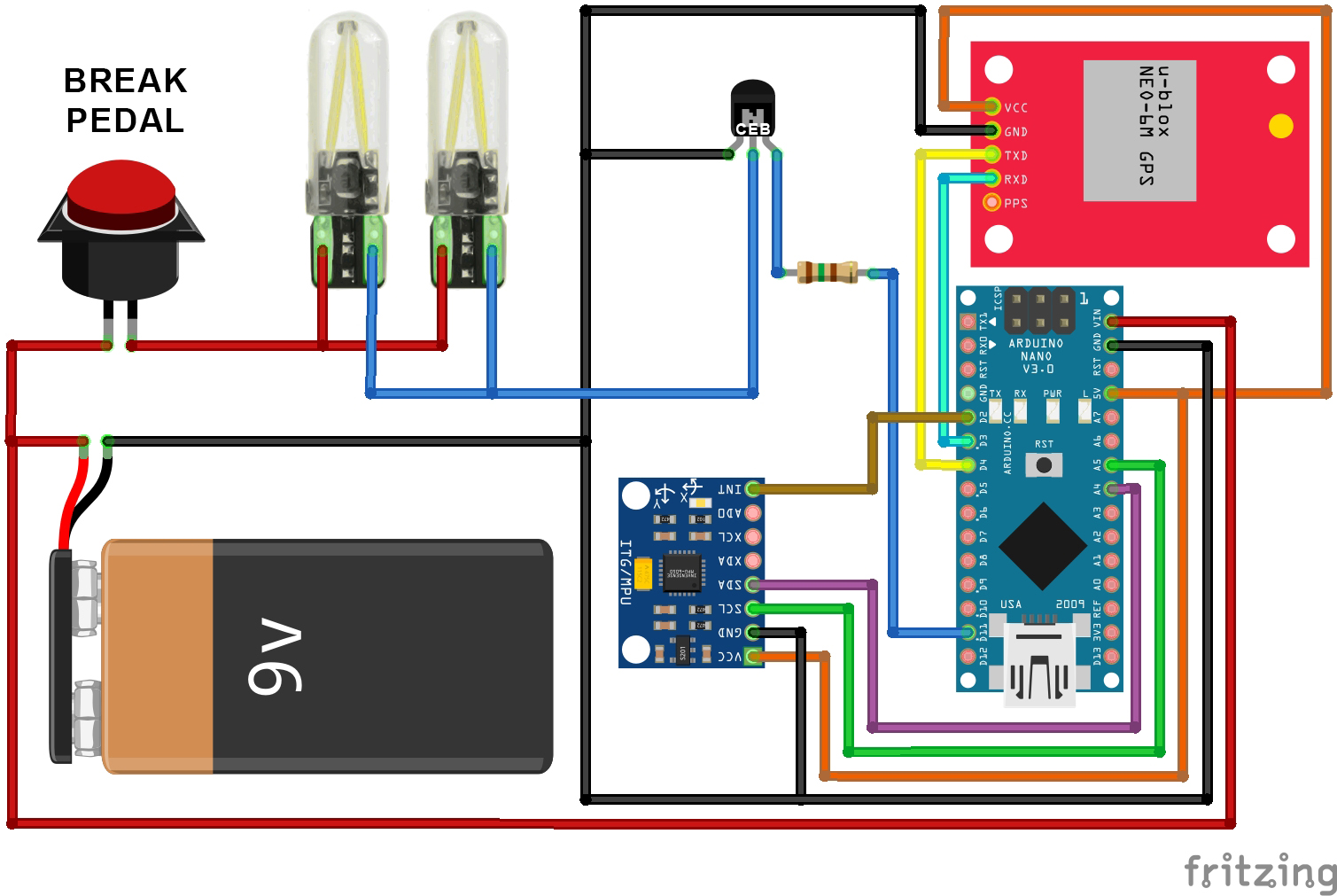
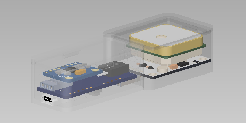
Microprocessor and accelerator module were soldered according to the circuit diagram (Fig. 1). The housings were 3D printed, a 3D render how the components were fitted inside is displayed in Fig. 2 below.
After uploading the program code, the acceleration sensor could also be read out via the USB port. The serial plotter of the Arduino IDE made it easy to display the output in real-time. For first tests it was sufficient to operate the system only via a USB port. Since the USB port only provides 5 V supply current, a 5 V LED was connected in the circuit for test purposes as shown in Fig. 3

This was followed by an analysis of the acceleration forces occurring in road traffic and – in order to determine the threshold value for emergency braking – also the (negative) acceleration during brake processes of varying intensity were examined. Fig. 4 shows the result of a test drive in the form of the data plot. The threshold value for emergency braking was thus set at 0.9 g.

On-road test
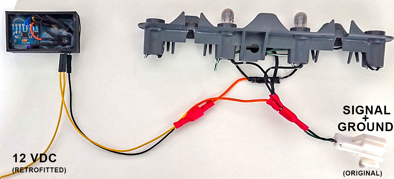
After determining the threshold value of the accelerating force of an emergency stop with 0.8 g, the system was connected to the vehicle network in a 12 V environment and connected between the negative pole of the brake light. The wiring was carried out as shown in Fig. 1. Two circuits are required: One continuous current to supply the Arduino with power continuously from the moment the ignition is activated until it is switched off. The second circuit is the brake light itself. Since current only flows here when the brake is also applied, this circuit is not a continuous current source and only supplies power to the bulbs. The signal is continuously fed through the microcontroller. The path of the brake light circuit through the microcontroller via the input IN and output Ground, which closes the circuit, led to minus. As it is not possible to show the wiring inside the vehicle, the specific parts were wired before for demonstration purposes as they were wired in the car later on. The setup is displayed in Figure 5. Optionally with connected GPS module, or not. The code is at least designed to work with and without a GPS module. With GPS module a speed threshold is active, without module only the G-value counts. A speed threshold of 80 km/h was set. The tests were successful, as the video (figure 6) proves.
While no action is triggered at 40 km/h and the threshold value of 0.8 g is exceeded and the brake light comes on normally, the sketch is activated above 80 km/h and the flashing is activated. For verification, braking above 80 km/h but below the threshold is also visible. As expected, the program does not trigger here.
Discussion & Outlook
In this project an adaptive brake light was retrofitted to an older vehicle.Above a threshold value of negative acceleration (g-force during braking) when a defined speed threshold is exceeded, the brake light starts flashing at a frequency below 0.5 Hz when actuated in order to alert following traffic about dangerous braking. The requirements for software and hardware are manageable at a maximum of $15 and represent a sensible investment for retrofitting your own vehicle – provided the legal requirements allow it. In an emergency, serious spinal cord injuries caused by a collision of the vehicle behind can be avoided. The vehicle’s acceleration and speed data can also be used in other projects, for example to implement anti-theft protection/GPS tracking.
Hello,
Thanks for sharing this great and important safety project!
I’m trying to figure out how I could use WS2812B LEDs instead of using bulbs.
I didn’t what risingEdge does in the code.
I will appreciate your help (:
Thanks,
Ariel
Hi Ariel,
In this project, the brake light of a vehicle was to be retrofitted with little effort. Surely the project can also be realized with addressable LEDs, but then it would be built and programmed quite differently.
risingEdge defines the timing at which the flashing sequence starts after the threshold value has been reached.
Hello what I have to change in the Sketch, to control only one axle not all 3?
In Hard corners I have wrong Brake flashing. So i only will control one axle.
Hi Pj,
the current sketch takes into account the acceleration due to the earth’s gravity when starting the controller. It is irrelevant in which orientation the module is installed in the vehicle.
A calculation of the longitudinal acceleration under neglect of transversal forces is possible in theory, but for this it is necessary that the module is installed in a fixed orientation in the vehicle. We did not want to do that here.
You can adjust the threshold values for velocity and G-force.
is that a 150ohm resistor that need to be included?
exactly
This is truly great, and what I was looking for for my motorcycle. Thanks for sharing!
During the read, I was wondering..
Could you have used a slightly different setup to make it ‘fail safe’? God forbid but when something breaks, could you have chosen a different intersecting semiconductor (in stead of the BD139) that passively keeps bridging the connection to ground? Or an inverted setup that bypasses the current switching the lights off .. that way – when the setup fails the original break light would remain functional. Which would give me peace of mind.
I’m sure there is a nifty solution for this that I’m obviously not smart enough to figure out… other than brute force it and install an additional break light 😉
I would be great if you would give this idea some consideration, 4 years after your original post!